Mars Helicopter Simulink-Based System Level Design
This example shows how to use Simscape™ Electrical™ and Aerospace Blockset™ to model a helicopter with coaxial rotors suitable to fly on Mars. This helicopter takes inspiration from Ingenuity, the robotic helicopter developed by NASA, which accomplished the first powered flight on another planet.
Model Overview
The helicopter model comprises a solar panel, a battery pack, a heater, a motor and drive, two gearboxes, two contra-rotating coaxial rotors, and a 1D mechanical model of the gravity, drag, mass, and ground contact forces.
The parameters for the elements in the model are saved in marsHelicopterSimulinkbasedSystemData.mat.
To open the model, use the following command:
model = 'marsHelicopterSimulinkbasedSystem';
open_system(model);
The Preload function loads the MAT-file and adds the struct 'ingenuityParams' to the workspace. The struct includes the environment and electrical and mechanical parameters of the model. To study the effects of different parameters on the system performance, you can change the values with the code in the marsHelicopterSimulinkbasedSystemParams.m file:
open('marsHelicopterSimulinkbasedSystemParams.m')
The basic overview of the Simulink® model is as shown:

The Battery System involves the solar panel and the batteries required to power the helicopter. The Motor and Drive and the Helicopter Model subsystems model the coaxial helicopter system, which produces the required thrust based on the reference torque input. The Control System, which consists of PID controllers, computes the reference torque based on the altitude command. To control the helicopter altitude interactively, use the blocks in the Command Dashboard subsystem.
Battery System
The Battery System consists of the Solar Panel, the Battery Pack, Heater, and an Ideal Semicondutor Switch.
The inputs to the system are the incident irradiance to the solar cell and the physical signal to the gate terminal of the ideal semiconductor switch.
The system outputs a bus signal, which consists of the state of charge (SOC) and temperature of the battery pack. This output signal determines when the Control System gets activated.

The Battery Pack is a Variant subsystem with two variant options, 'Detailed Battery Pack' and the 'Simplified Battery Pack'.
Select the appropriate variant based on use case. In the Simulink toolstrip, select Variant Subsystem > Open and click a variant from the list. Alternatively, you can use the function 'marsHelicopterSimulinkbasedSystemSetBattery' to select the appropriate variant as shown here:
batteryVariant = 'Detailed'; % batteryVariant = 'Simplified';
marsHelicopterSimulinkbasedSystemSetBattery(model, batteryVariant);
Detailed Battery Pack
The battery pack contains six lithium-ion cells connected in series. Only the central cell is instrumented. The Heater is attached to the central cell. The cells transfer heat to each other and to the insulating box, which dissipates heat to the martian environment.

Simplified Battery Pack
The battery pack in this case contains a single lithium-ion cell.

By default, the 'Detailed Battery Pack' variant is selected.
To correctly size the battery pack, consider the nominal voltage of the motor drive and the required nominal power, the nominal flight duration, the payload weight, and the battery energy to weight ratio. Additionally, the solar panel size and the average sun irradiation, together with the heat required to sustain the minimum temperature during the cold martian nights, determine the minimum and maximum energy that you can store during each daily cycle.
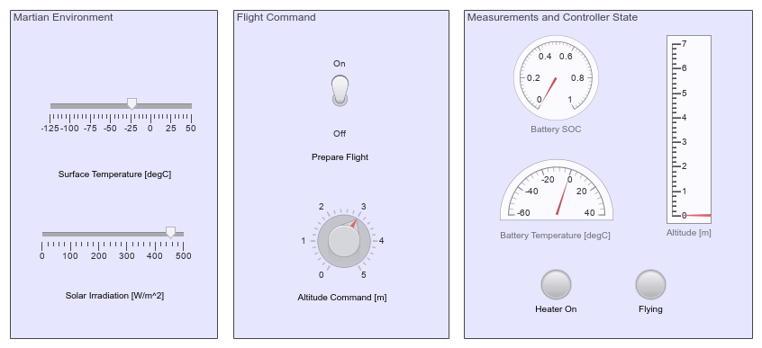
Command Dashboard
To control the helicopter interactively during the simulation, use the Sliders, Switches, and Knob blocks in the Command Dashboard subsystem.
As the model solves the equations much faster than real time, simulation pacing is enabled to slow down the animations to only 30 times faster than real time.
Control System
The helicopter must survive the cold martian nights, which can reach temperatures as low as -125 degC (-193 degF). The electronics and batteries cannot operate at such temperatures, so a heater (part of the Battery system) keeps the temperatures in an acceptable range.
The rotors consume high amounts of power during flight, but the batteries can only provide such power above certain temperatures. As a result, before taking off, we must use the heater to reach these temperatures.
The inputs to the control system include the battery bus signal (SOC and temperature) and the mechanical speed of the Motor and Drive subsystem.

To implement the logic to turn on or off the triggered 'Flight Controller' subsystem, use the state chart 'System-Level Controls'. Based on the battery conditions and the altitude command input, the state chart also provides the reference altitude. The necessary conditions for flight ('Fly' state) in this scenario are:
Temperature (T) must be above 10 degC (50 degF).
SOC must be above 0.3.

The reference altitude, measured altitude, and the mechanical speed form inputs to the Flight Controller subsystem. Once the helicopter is ready to fly, the Flight Controller subsystem is enabled to control the altitude. The Flight Controller subsystem comprises three PIDs that control the rotor speed, the climb rate, and the altitude. The output is the reference torque for the Motor and Drive subsystem.

Motor and Drive
The reference torque as computed by the Flight Controller is input to the Motor & Drive block. This block then provides the torque input to the two rotors of the Helicopter system via respective gear boxes.

Helicopter Model

The positive and negative gear boxes signify that in the coaxial system, the two rotors rotate at the same speed but in opposite directions, thereby balancing the torque. In this specific scenario, blade pitch control is not considered. The Mechanical forces & Sensors subsystem represent the body and landing gear of the helicopter (mass and contact forces).
The Rotor block is an Aerospace Blockset block, therefore interface subsystem blocks are used to convert between the physical (Simscape) and Simulink signals. The interfaces are used at the input (rotational) and output (translational) end of the rotor system. The required inputs to the Rotor block are the rotational velocity and the density. The rotor, in this scenario, performs pure vertical motion, therefore there exists no significance in including flap dynamics.
As a result, the modeling approach in the Rotor block is set to 'Without flap effects'. In this case, the required parameters directly input to the block are the thrust, torque coefficients, and the blade radius.

The Simscape Rotational Interface, using an Ideal Torque Source and Ideal Rotational Motion Sensor, computes the required rotational velocity from the input torque.

The outputs from the Rotor block are the forces and moments in all three dimensions. In this scenario, sole interest is in the force in the z-direction and moment about z-axis. The Rotor block uses a z-downward positive convention. To compensate for the difference in convention, a negative gain is added.
The Simscape Translational Interface using an Ideal Force Source computes the equivalent translational velocity from the input force, which is used in the control system for the computation of altitude.

Results
Simulate the Model
To simulate the model with 'Detailed' Battery Pack enabled:
if ~exist('outMarsHelicopterSimulinkbasedSystem', 'var') || ...
        ~strcmp(get_param([model, '/Battery System/Battery Pack'], 'LabelModeActiveChoice'), 'Detailed Battery Pack')
    set_param([model, '/Battery System/Battery Pack'], 'LabelModeActiveChoice', 'Detailed Battery Pack')
    set_param(model, 'EnablePacing', 'off');
    out = sim(model);
    set_param(model, 'EnablePacing', 'on');
else
    out = outMarsHelicopterSimulinkbasedSystem;
end
Plot Altitude and Battery Cell Temperatures
The 'Altitude' scope displays the variation in altitude over the entire duration.
The altitude and battery cell temperature variation are plotted below:
simlog = out.simlog_marsHelicopterSimulinkbasedSystem;
tout = simlog.Helicopter_Model.Mechanical_Forces_Sensors.Ideal_Translational_Motion_Sensor.x.series.time;
altitude = simlog.Helicopter_Model.Mechanical_Forces_Sensors.Ideal_Translational_Motion_Sensor.x.series.values('m');
fig_plot1 = figure('Name', 'marsHelicopterSimulinkbasedSystemPlot1');
figure(fig_plot1)
clf(fig_plot1)
subplot(2,1,1)
plot(tout, altitude,'b--', 'LineWidth',1.5)
grid on
xlabel('Time [s]')
ylabel('Altitude [m]')
title('Altimeter measurements')

tout = simlog.Battery_System.Battery_Pack.Detailed_Battery_Pack.Cell1.cell_temperature.series.time;
T1 = simlog.Battery_System.Battery_Pack.Detailed_Battery_Pack.Cell1.cell_temperature.series.values('degC');
T2 = simlog.Battery_System.Battery_Pack.Detailed_Battery_Pack.Cell2.cell_temperature.series.values('degC');
T3 = simlog.Battery_System.Battery_Pack.Detailed_Battery_Pack.Cell3.cell_temperature.series.values('degC');
T4 = simlog.Battery_System.Battery_Pack.Detailed_Battery_Pack.Cell4.cell_temperature.series.values('degC');
T5 = simlog.Battery_System.Battery_Pack.Detailed_Battery_Pack.Cell5.cell_temperature.series.values('degC');
T6 = simlog.Battery_System.Battery_Pack.Detailed_Battery_Pack.Cell6.cell_temperature.series.values('degC');

subplot(2,1,2)
colorOrder = hot(10);
plot(tout, [T1,T2,T3,T4,T5,T6], '-.','LineWidth',1.5);
grid on
set(gca, 'ColorOrder', colorOrder)

xlabel('Time [s]');
ylabel('Temperature [degC]');
title('Battery cell temperatures');
legend({'C1', 'C2', 'C3', 'C4', 'C5', 'C6'});

% Clean-up
clear out colorOrder simlog tout altitude T1 T2 T3 T4 T5 T6
As can be observed from the results, the helicopter moves to the 'Fly' state when the battery temperature reaches the required value of 10 degC (50 degF) and moves towards the reference altitude of 3m. The 'Land' state is initiated when the battery SOC falls below the value of 0.3.
Plot Flight Duration Against Number of Battery Cells
The total number of batteries directly influences the maximum possible duration of the flight. To provide more energy storage, you can add more batteries. However, doing so also increases the weight of the vehicle. Eventually, the motor will be unable to provide enough power to lift the extra weight.
The following task studies the effect of number of additional batteries on the flight duration.
1. Setup
Save the original model parameters to restore at the end of the task:
ingenuityParamsOriginal = ingenuityParams;
T_marsOriginal = str2double(get_param([model, '/Tenv'], 'Value'));
Irr_marsOriginal = str2double(get_param([model, '/Irradiation'], 'Value'));
missionAltitudeOriginal = str2double(get_param([model, '/altCom'], 'Value'));
For this simulation, adjust the environment parameters to a desired value:
T_mars =-10; % Mars surface temperature, in degC Irr_mars =
0; % Mars incident solar irradiation, in W/m^2 set_param([model, '/Tenv'], 'Value', num2str(T_mars)); set_param([model, '/Irradiation'], 'Value', num2str(Irr_mars));
Input the initial battery temperature and state of charge:
ingenuityParams.battery.cell.T_init =-10; % Battery initial temperature, in degC ingenuityParams.battery.cell.SOC_init = 0.97;
Choose the range of number of parellel strings of 6 cells to consider (numStringsMin:1:numStringsMax) and select the Simplified Battery Pack variant:
numStringsMin =1; numStringsMax =
6; set_param([model, '/Battery System/Battery Pack'], 'LabelModeActiveChoice', 'Simplified Battery Pack');
Adjust the simulation stop time and disable simulation pacing and fast restart to increase speed:
set_param(model, 'StopTime', '2000');
set_param(model, 'EnablePacing', 'off');
Input the altitude command and prepare flight at the start of the simulation:
missionAltitude =5; % Target altitude, in m set_param([model, '/altCom'], 'Value', num2str(missionAltitude)); set_param([model, '/prepFlight'], 'Value', '1');
2. Run Simulations
Simulink.SimulinkInput object is used to specify the varying parameters for the model.
numStringsVec = numStringsMin:1:numStringsMax;

simin(1:length(numStringsVec)) = Simulink.SimulationInput(model);

for i = 1:length(numStringsVec)
    thisNumStrings = numStringsVec(i);
    simin(i) = simin(i).setVariable('ingenuityParams.battery.numParallelStrings',thisNumStrings);
    simin(i) = simin(i).setVariable('ingenuityParams.battery.numCells',thisNumStrings*ingenuityParams.battery.numSeriesCells);
end

simout = sim(simin,'ShowProgress','off');
To simulate the model multiple times using varying parameters, parsim function may be used as shown:
simout = parsim(simin,'UseFastRestart','on','ShowProgress','off');
Reset model to original settings:
set_param(model, 'StopTime', '15*60');
set_param(model, 'EnablePacing', 'on');
ingenuityParams = ingenuityParamsOriginal;
set_param([model, '/Tenv'], 'Value', num2str(T_marsOriginal));
set_param([model, '/Irradiation'], 'Value', num2str(Irr_marsOriginal));
set_param([model, '/altCom'], 'Value', num2str(missionAltitudeOriginal));
set_param([model, '/Battery System/Battery Pack'], 'LabelModeActiveChoice', 'Detailed Battery Pack')
3. Analyze Results
Plot each trajectory and flight duration:
if ~exist('fig_plot2', 'var') || ...
        ~isgraphics(fig_plot2, 'figure')
    fig_plot2 = figure('Name', 'marsHelicopterSimulinkbasedSystemPlot2');
end
figure(fig_plot2);
clf(fig_plot2);

subplot(1,2,1);
flightDurationVec = nan(size(numStringsVec));
colorOrder = winter(length(numStringsVec)+1);
for i = 1:length(numStringsVec)
    thisAltitude = simout(i).simlog_marsHelicopterSimulinkbasedSystem.Helicopter_Model.Mechanical_Forces_Sensors.Ideal_Translational_Motion_Sensor.x.series.values('m');
    thisTimeVec = simout(i).simlog_marsHelicopterSimulinkbasedSystem.Helicopter_Model.Mechanical_Forces_Sensors.Ideal_Translational_Motion_Sensor.x.series.time;
    % Compute flight duration
    timeStartFly = thisTimeVec(find(thisAltitude > missionAltitude/100, 1, 'first'));
    if isempty(timeStartFly) % Could not take off
        flightDurationVec(i) = 0;
    else
        timeEndFly = thisTimeVec(find( (thisAltitude < missionAltitude/100) & (thisTimeVec > timeStartFly), 1, 'first'));
        flightDurationVec(i) = timeEndFly - timeStartFly;
    end
    % Plot trajectory
    plot(thisTimeVec, thisAltitude, "--", "LineWidth", 1.5);
    hold on
end
set(gca, 'ColorOrder', colorOrder)
grid on
hold off
xlabel('Time [s]')
ylabel('Altitude [m]')
xlim([0, thisTimeVec(end)])
title('Trajectories')

% Plot flight duration vs number of cells
subplot(1,2,2)
plot(numStringsVec, flightDurationVec, 'rx-', "LineWidth", 1.0, 'MarkerSize', 10);
xlim([numStringsVec(1), numStringsVec(end)])
xticks(numStringsVec)
grid on
xlabel(['Number of parallel strings of ', num2str(ingenuityParams.battery.numSeriesCells), ' cells'])
ylabel('Maximum flight duration [s]')
title('Flight duration')

%Clean-up
clear colorOrder flightDurationVec i ingenuityParamsOriginal Irr_mars missionAltitude model numStringsMax
clear numStringsMin numStringsVec simout T_mars thisAltitude thisNumStrings thisTimeVec timeEndFly timeStartFly
clear Irr_marsOriginal missionAltitudeOriginal T_marsOriginal
As seen in these plots, increasing the number of batteries increases the vehicle weight such that the motor can no longer provide sufficient power to lift the vehicle.
References
NASA. Ingenuity Mars Helicopter, Landing Press Kit. Available online: Ingenuity Mars Helicopter
See Also
Blocks
Objects
Related Topics
You can also select a web site from the following list:
Americas
- América Latina (Español)
- Canada (English)
- United States (English)
Europe
- Belgium (English)
- Denmark (English)
- Deutschland (Deutsch)
- España (Español)
- Finland (English)
- France (Français)
- Ireland (English)
- Italia (Italiano)
- Luxembourg (English)
- Netherlands (English)
- Norway (English)
- Österreich (Deutsch)
- Portugal (English)
- Sweden (English)
- Switzerland
- United Kingdom (English)