PID Controller Design in the Live Editor
This example shows how to use the Tune PID Controller task in the Live Editor to generate code for designing a PID controller for a linear plant model. The Tune PID Controller task lets you interactively refine the performance of the controller to adjust loop bandwidth and phase margin, or to favor setpoint tracking or disturbance. The task generates a response plot that lets you monitor controller performance while you adjust the tuning parameters.
Open this example to see a preconfigured script containing the Tune PID Controller task. For more information about Live Editor tasks generally, see Add Interactive Tasks to a Live Script.
In the Live Editor, create an LTI model for your plant.
G = zpk(-5,[-1 -2 -3 -4],6);
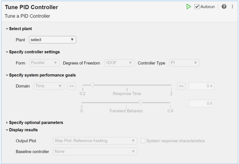
To design a PID controller for this plant, open the Tune PID Controller Live Editor task. On the Live Editor tab, select Task > Tune PID Controller. This action inserts the task into your script.
Initial Controller Design
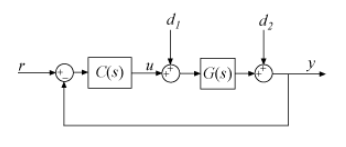
To generate an initial PID controller design, in the Plant menu, select the plant you created, G. Tune PID Controller automatically generates a PI controller that balances performance and robustness, assuming the standard unit-feedback control configuration of the following diagram.
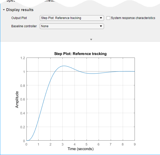
The task also generates a step response plot showing the closed-loop step response from r to y using the initial controller design.
Refine Controller Design
Select System response characteristics to display numeric values of some time-domain characteristics of this response.
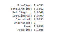
The initial controller design has a rise time of about 1.5 seconds, with about 8% overshoot. Experiment with the Response Time and Transient Behavior sliders to change the design targets and see their effect on the step response.
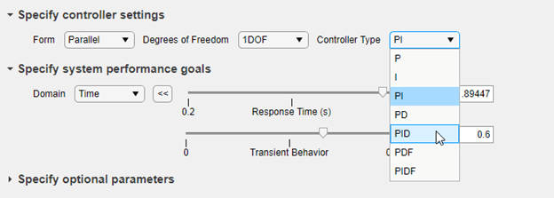
With a PI controller and this plant, it is difficult to decrease the response time without introducing instability or otherwise degrading system response. Try switching to a PID controller to see if you can achieve a better response time. In the Controller Type drop-down menu, select PID.
You can now reduce the response time of the controller. Experiment with the sliders again, observing the effect on the step response. For an example that shows in more detail how the Response Time and Transient Behavior sliders affect controller performance, see Tune PID Controller to Favor Reference Tracking or Disturbance Rejection (PID Tuner). That example uses the PID Tuner app instead of the Tune PID Controller task in the Live Editor, but the behavior and effect of the sliders is the same in both tools.
Examine Generated Code
The task automatically generates code to tune a PID controller for the plant with the specified design goals. To see the generated code, click ![]() Show code at the bottom of the task. The task expands to show the generated code.
Show code at the bottom of the task. The task expands to show the generated code.
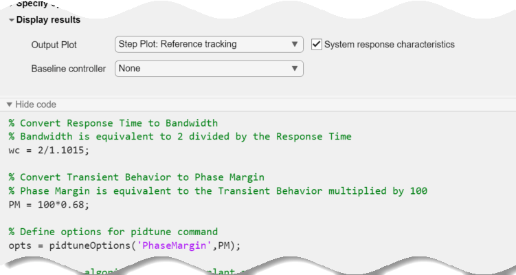
As you change parameters such as controller structure, performance goals, and response-plot type, the generate code updates automatically to reflect the new settings.
Examine Disturbance Rejection Performance
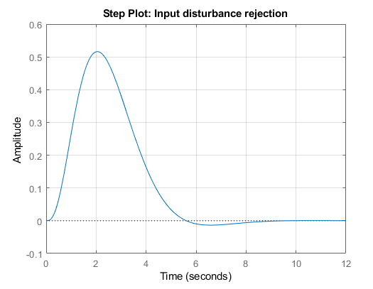
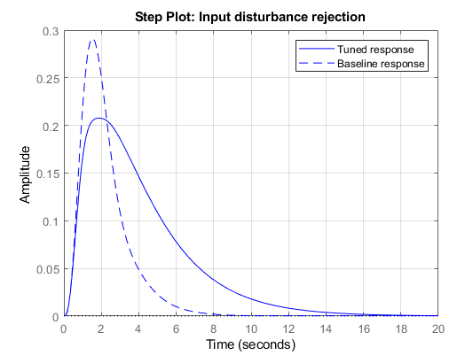
Suppose that you are interested in the closed-loop system response to a disturbance at the plant input. To generate a plot of the step response from to y, in the Output Plot drop-down menu, select Step Plot: Input disturbance rejection. The plot updates to show the new response. Depending on how you set the performance goals when you change the response plot, you might see a response that looks like the following.
You can now experiment again with controller parameters and observe their effect on disturbance rejection. For an example that shows in more detail how you can use the sliders and other design parameters to improve disturbance rejection performance, see Tune PID Controller to Favor Reference Tracking or Disturbance Rejection (PID Tuner). That example uses the PID Tuner app instead of the Tune PID Controller task in the Live Editor, but the behavior and effect of design parameters is the same in both tools.
Compare Two Controller Designs
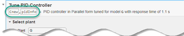
Tune PID Controller automatically writes the tuned controller to the MATLAB® workspace as a pid, pidstd, pid2, or pidstd2 model object, whichever is appropriate for your controller settings. The task stores the controller using the variable name specified in the task summary line. By default, that variable name is C. When you change controller settings, performance goals, or other tuning parameters, by default the task writes over the variable C.
You can save a controller design to use as a baseline for comparison while you experiment further with controller types, performance goals, and other settings. To do so, type a new variable name in the task summary line. For instance, change the output controller name to Cnew.
Now, the current design is stored in the MATLAB workspace as C. Any further changes to the design are stored as Cnew.
To use C as a baseline for comparison, in the Baseline controller menu, choose Select from workspace. Then, select C in the menu that appears.
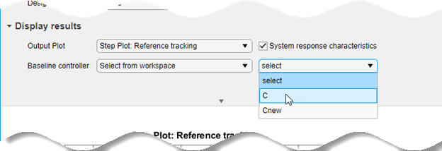
Now, as you experiment further with the controller design, the plot displays both the system response with controller C (dotted line) and with controller Cnew (solid line).
Use the Controller
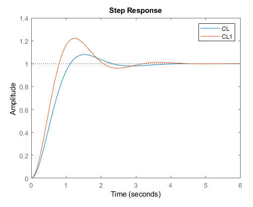
Because the Tune PID Controller task saves the controller to the MATLAB workspace, you can use the controller as you would use any other PID model object for control design and analysis. For instance, examine the controller performance against a slightly different plant model, to get a sense of the robustness of the closed-loop system against parameter variation.
G1 = zpk(-5,[-0.75 -2 -3 -4],8);
CL1 = getPIDLoopResponse(C,G1,'closed-loop');
CL = getPIDLoopResponse(C,G,'closed-loop');
step(CL,CL1)