EV Battery Cooling System Design
This example explores several questions related to heat exchanger sizing and system performance. The example answers the questions using fundamental heat transfer principles, and then confirms the behavior in test harness models and a full system model.
System Introduction
The simplified electric vehicle cooling system model in this example focuses on steady thermal behavior over a short time frame. See Electric Vehicle Thermal Management for a more detailed electric vehicle cooling system model with transient and time-varying dynamics.
The battery generates heat. The battery operates at peak performance over a limited temperature range. The battery cooling system uses ethylene glycol coolant flowing through several heat exchangers to keep the battery operating at the optimal temperature. The heat exchangers include:
Cold Plate: Heat flows from the battery to coolant.
Radiator: Heat flows from the coolant to air.
Refrigeration system: Heat flows from the coolant to refrigerant in an evaporator.
This example examines the cooling system behavior in two scenarios. In the first scenario, the environment temperature is 0 degC, and all of the coolant flows through the radiator. When the environment temperature is cold, the radiator alone is sufficient for cooling the coolant. In the second scenario, the environment temperature is 30 degC, and all of the coolant flows through the evaporator. In both scenarios, the vehicle travels at the same speed, and the battery draws the same amount of current.
Cooling Scenario | 1 | 2 |
Vehicle Speed (m/s) | 30 | 30 |
Battery Current (A) | 40 | 40 |
Environment Temperature (degC) | 0 | 30 |
Open the model.
open_system('EVBatteryCoolingSystemDesign');
Question 1: Size the Cold Plate
A cold plate maintains the battery temperature at 20 degC while the battery draws 40 A current.
A) How much heat must the coolant absorb?
B) What is the coolant temperature at the cold plate outlet?
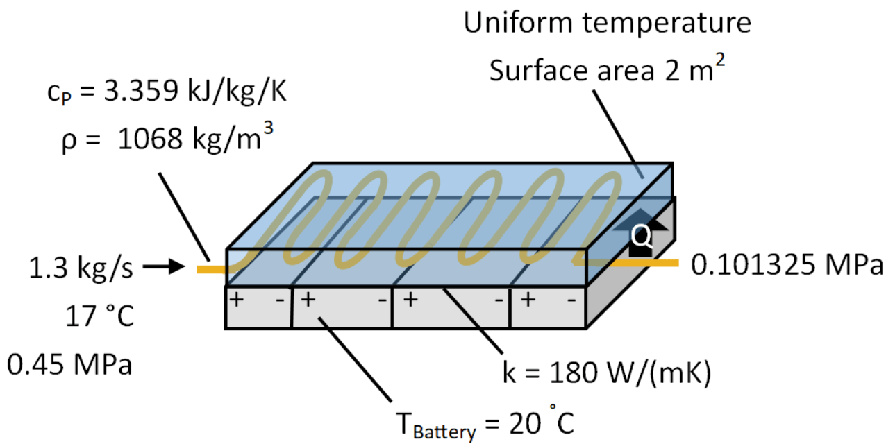
Make the following assumptions:
The battery resistance is a function of temperature as described below.
The battery resistance is 6.25 Ohms when the battery temperature is 20 degC.
The only heat transfer from the battery is conduction to the cold plate.
The cold plate maintains a uniform temperature.
The total effective conduction coefficient from the battery to cold plate is 180 W/(mK).
The effective surface thickness for conduction is 8 mm.
The area of contact between the battery and cold plate is 2 m^2.
The coolant flow rate is 1.3 kg/s.
The coolant at the cold plate inlet has a temperature of 17 degC and pressure of 0.45 MPa.
The coolant at the cold plate outlet is at atmospheric pressure, 0.101325 MPa.
The coolant has a specific heat at constant pressure of 3.359 kJ/kg/K and density of 1068 kg/m^3 in the cold plate channel.
Battery Resistance
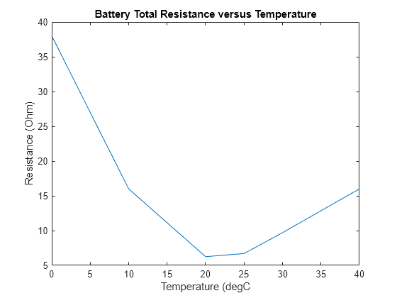
The battery resistance generates heat. The battery resistance is a function of the state of charge and temperature. Below is a plot of the battery resistance as a function of temperature assuming a fixed state of charge.
TreferenceBattery = [0    10   20    25    30    40]; % [degC]
RreferenceBattery = [38   16   6.25   6.7  9.7   16]; % [Ohm]

plot(TreferenceBattery, RreferenceBattery);
title('Battery Total Resistance versus Temperature')
xlabel('Temperature (degC')
ylabel('Resistance (Ohm)')
How Much Heat Does the Battery Generate?
Heat generated by the battery resistance is
Where:
is the battery current.
is the battery resistance.
The battery has a resistance of 6.25 Ohms at 20 deg C.
Calculate the generated heat at the given battery current and target temperature.
TTargetBattery = 20; % [degC]
R = 6.25; % [degC]
I = 40; % [A]
Q = I^2*R / 1000 % Generated heat [kW]
Q =
10
What Is the Coolant Temperature at the Cold Plate Outlet?
The coolant absorbs the heat generated by the battery. The steady-flow thermal energy equation, accounting for pressure drop along the pipe, is
Where:
is the coolant mass flow rate.
is the coolant specific heat at constant pressure.
is the coolant temperature at the cold plate inlet.
is the coolant temperature at the cold plate outlet.
is the coolant pressure at the cold plate inlet.
is the coolant pressure at the cold plate outlet.
is the coolant density.
Solve the equation for .
TInCoolantPlate = 17;          % [degC]
pInCoolantPlate = 0.4535;      % [MPa]
pOutCoolantPlate = 0.101325;   % [MPa]

mDotCoolant = 1.3;             % [kg/s]

cpCoolant = 3.359;             % [kJ/kg/K] Specific heat at constant pressure
rhoCoolant = 1068;             % [Kg/m^3] Density

TOutCoolantPlate = ( Q / mDotCoolant - (pOutCoolantPlate - pInCoolantPlate)*1e3/rhoCoolant ) / cpCoolant + TInCoolantPlate
TOutCoolantPlate =
19.3882
The coolant gains 2.4 degC as it flows through the cold plate channel.
Check the Behavior in a Test Harness
Open the test harness for the battery and cold plate.
open_system('EVBatteryCoolingSystemDesignBatteryHarness'); 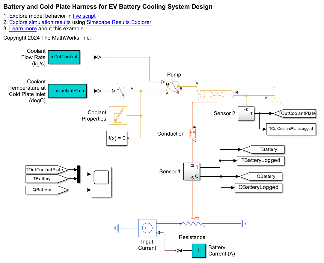
The test harness isolates the battery and cold plate from the rest of the battery cooling system. The test harness has fixed boundary conditions for the coolant at the cold plate inlet and outlet.
Simulate the test harness.
sim('EVBatteryCoolingSystemDesignBatteryHarness');
QBatterySimulated = QBatteryLogged(end) % [kW]
QBatterySimulated =
10.0309
TBatterySimulated = TBatteryLogged(end) % [degC]TBatterySimulated = 19.9802
TOutCoolantPlateSimulated = TOutCoolantPlateLogged(end) % [degC]TOutCoolantPlateSimulated = 19.4029
The simulated heat flow rate, battery temperature, and coolant outlet temperature agree closely with the expected values. The slight discrepancies between the calculated and simulated values are due to how the simulation uses thermal liquid properties that are a function of pressure and temperature while the calculations assume that the properties are constant.
Question 2: Size the Radiator for Scenario 1
On a cold day, the radiator alone can sufficiently cool the coolant, so all of the coolant flows through the radiator, and none of the coolant flows through the refrigeration system. What are the required heat transfer surface areas between the coolant and the air to cool the coolant from 19.4 degC to 17.1 degC?
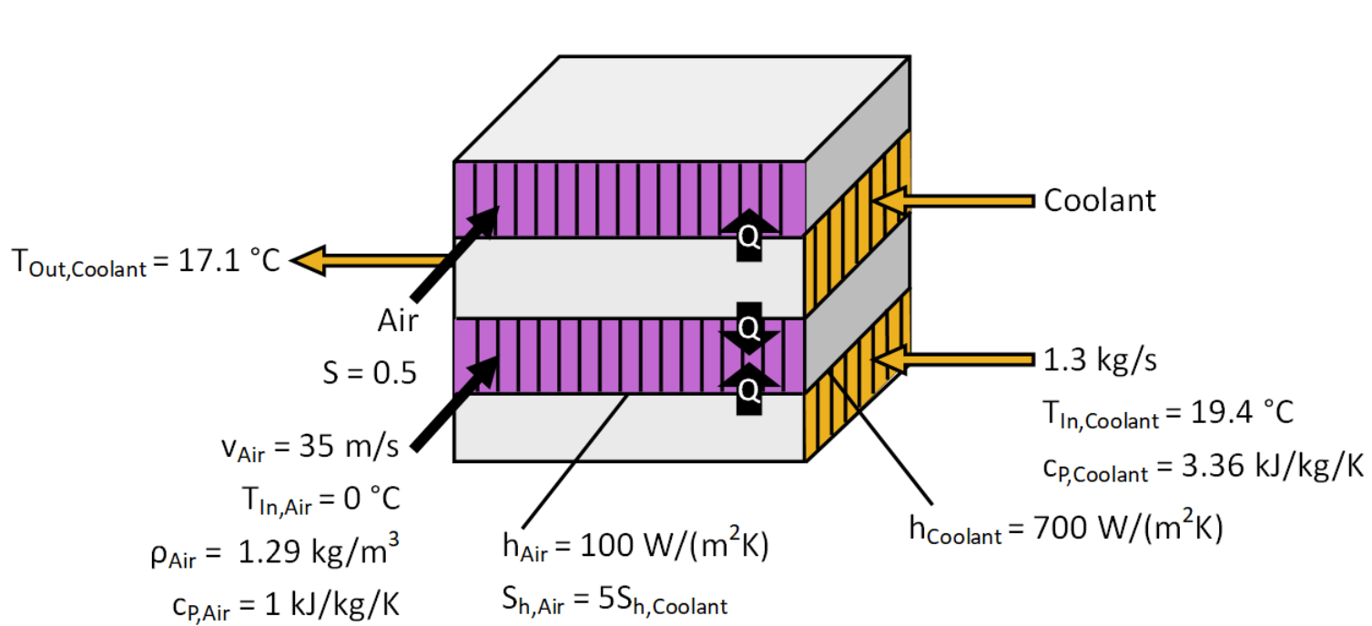
Make the following assumptions:
The radiator is a single-pass cross-flow heat exchanger.
Air enters the radiator at the environment temperature of 0 degC.
A fan adds 5 m/s velocity to the air velocity through the radiator in addition to the vehicle speed of 30 m/s.
Air flows through a total cross-sectional area of 0.5 m^2.
Coolant enters the radiator at 19.4 degC.
Coolant leaves the radiator at 17.1 degC.
Coolant flows at a rate of 1.3 kg/s.
Heat transfer coefficient between the air and interface wall is 100 W/m^2/K.
Heat transfer coefficient between the coolant and interface wall is 700 W/m^2/K.
The heat transfer surface area of the air is 7 times larger than heat transfer surface area of the coolant.
Using fins to increase the air-side surface area by seven compensates for the air's convective heat transfer coefficient being seven times smaller than that of the coolant. This balance ensures optimal heat transfer efficiency by equalizing the heat transfer capacity on both sides.
Create MATLAB® variables to define the problem assumptions.
% Scenario
Tenvironment = 0; % [degC]
vVehicle = 30;    % [m/s]

% Air scenario, properties, and fixed design parameters
TInAirRadiator = Tenvironment;   % [degC]
SAir = 0.5;                      % [m^2] Cross-sectional area for air flow
vAirFanBoost = 5;                % Added velocity due to fan [m/s]
hAir = 100;                      % [W/m^2/K] Constant convective heat transfer coefficient
ShRatioAirToCoolantRadiator = 7; % Ratio of heat transfer surface areas

% Air properties at environment temperature and 1 atm
cpAir = 1;     % [kJ/kg/K] Specific heat at constant pressure
rhoAir = 1.29; % [kg/m^3] Density

% Coolant scenario, properties, and fixed design parameters
mDotCoolant = 1.3;          % [Kg/s] Mass flow rate
TInCoolantRadiator = 19.4;  % [degC] Coolant temperature at radiator inlet
TOutCoolantRadiator = 17.1; % [degC] Coolant temperature at radiator outlet
hCoolantRadiator = 700;     % [W/m^2/K] Constant convective heat transfer coefficient

% Coolant properties at 18 degC and 1 atm
cpCoolant = 3.358; % [kJ/kg/K]
Determine the heat capacity rates.
The heat capacity rate for the air is
Where:
is the air mass flow rate.
is the air specific heat at constant pressure.
The air mass flow rate is equal to
Where:
is the air density.
is the cross-sectional area for air flow.
is the vehicle velocity.
is the air specific heat at constant pressure.
mDotAir = rhoAir * SAir * (vVehicle + vAirFanBoost); % [kg/s]
CAir = mDotAir * cpAir % [kW/K] Air heat capacity rate
CAir =
22.5750
The heat capacity rate for the coolant is
Where:
is the coolant mass flow rate.
is the coolant specific heat at constant pressure.
CCoolant = mDotCoolant * cpCoolant % [kW/K] Coolant heat capacity rateCCoolant = 4.3654
The coolant has the minimum heat capacity rate
Cmin = min(CAir, CCoolant); % [kW/K]The maximum heat transfer is
.
qMax = Cmin * (TInCoolantRadiator - TInAirRadiator) % [kW]qMax = 84.6888
The actual heat transfer is
.
q = CCoolant * (TInCoolantRadiator - TOutCoolantRadiator) % [kW]q = 10.0404
The radiator effectiveness is
.
effectiveness = q / qMax
effectiveness =
0.1186
The heat capacity ratio is
.
Cmax = max(CAir, CCoolant); % [kJ/K/s]
Cr = Cmin / Cmax
Cr = 0.1934
Determine the number of transfer units. For a cross-flow heat exchanger with both fluids unmixed and a single-pass, the effectiveness as a function of the heat capacity ratio and NTU is
Use a plot to visualize the relationship of effectiveness to NTU for the heat capacity ratio.
NTUcurve = 0:0.1:5;
effectivenessCurve = 1 - exp(1/Cr * NTUcurve.^0.22 .* (exp(-Cr*NTUcurve.^0.78) -1) );
figure;
plot(NTUcurve, effectivenessCurve)
xlabel('NTU');
ylabel('\epsilon')
title({'Effectiveness of a Single-Pass Cross Flow heat exchanger', ['with Both Fluids Unmixed and Cr = ' num2str(Cr,4)]})
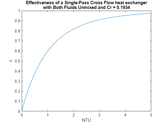
The figure indicates that for an effectiveness of 0.12, the NTU is approximately 0.12.
Use the fzero function to solve for the precise value of NTU near 0.12 that satisfies the cross-flow heat exchanger effectiveness equation.
eNTUfunction = @(NTU) effectiveness - (1 - exp(1/Cr * NTU^0.22 .* (exp(-Cr*NTU^0.78) -1) ) ); % effectiveness - f(Cr, NTU) = 0

NTU = fzero(eNTUfunction, 0.12)
NTU = 0.1287
NTU relates to the overall heat transfer coefficient by
where is the overall heat transfer coefficient.
The overall heat transfer coefficient, , relates to the fluid heat transfer coefficients by
where:
is the convective heat transfer coefficient of the air.
is the heat transfer surface area of the air.
is the convective heat transfer coefficient of the coolant.
is the heat transfer surface area of the coolant.
The heat transfer surface area of the air is seven times larger than the heat transfer surface area of the coolant. That is,
.
Combine equations and solve for the required surface area of the coolant
.
ShCoolantRadiator = (Cmin * 1000) * NTU * (1 / (7*hAir) + 1 / hCoolantRadiator) % [m^2]ShCoolantRadiator = 1.6049
Calculate the required surface area for the air-side of the heat exchanger.
ShAir = 7 * ShCoolantRadiator % [m^2]ShAir = 11.2344
Check the Behavior in a Test Harness
Compare the calculated response to the Simscape™ simulated response.
open_system('EVBatteryCoolingSystemDesignRadiatorHarness');
open_system('EVBatteryCoolingSystemDesignRadiatorHarness/Radiator');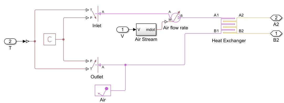
The test harness isolates the radiator from the rest of the battery cooling system. The test harness has fixed mass flow rates and boundary conditions at the inlets and outlets for both the coolant and air.
Simulate the test harness.
sim('EVBatteryCoolingSystemDesignRadiatorHarness');
TOutCoolantRadiatorSimulated = TOutCoolantRadiatorLogged(end) % [degC]
TOutCoolantRadiatorSimulated =
17.0950
At the design point, the radiator cools the Coolant from 19.4 degC to 17.1 degC, as expected. The slight discrepancies between the calculated and simulated values are due to how the simulation uses thermal liquid properties that are a function of pressure and temperature while the calculations assume the properties are constant.
Check the Behavior in the Full Model
Configure the model to direct all coolant through the radiator by setting the valve control signal to 0. Then simulate the model.
open_system('EVBatteryCoolingSystemDesign');

valveOpeningFraction = 0;

sim('EVBatteryCoolingSystemDesign');

% Check simulated results
TBatteryLogged(end) % [degC]
ans =
19.9777
QBatteryLogged(end) % [kW]ans = 10.0348
TInCoolantHXLogged(end) % Coolant temperature at radiator inlet [degC]ans = 19.4006
TOutCoolantHXLogged(end) % Coolant temperature at radiator outlet [degC]ans = 17.0955
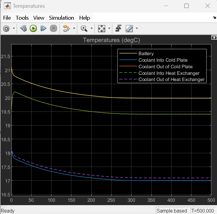
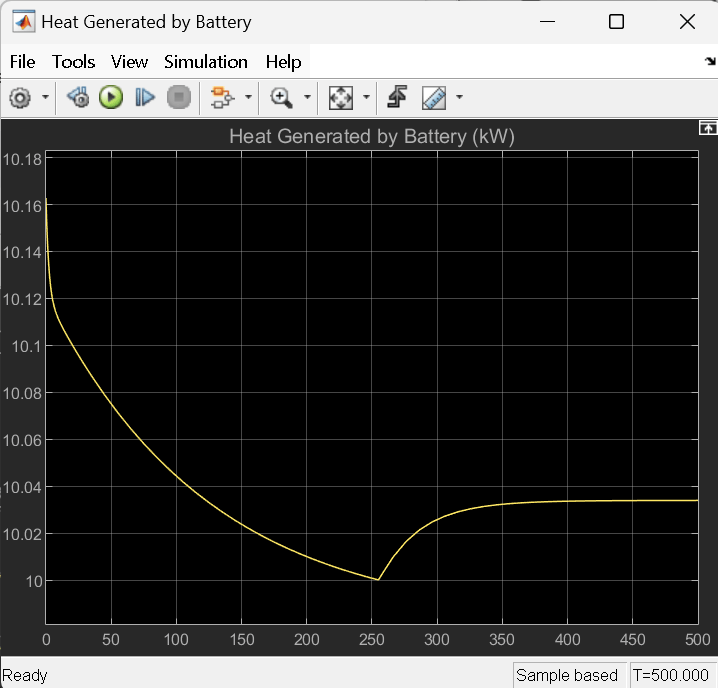
In the full model, the cooling system maintains the battery at a temperature of 20 degC. The radiator cools the coolant from 19.4 degC at the inlet to 17.1 degC at the outlet.
Question 3: Size the Evaporator for Scenario 2
On a hot day, the environmental air temperature exceeds the optimal battery temperature. Therefore, a radiator cannot cool the coolant and all of the coolant flows through the evaporator of a refrigeration system. In the evaporator, heat transfers from the coolant to the refrigerant.
A) What is the required mass flow rate of the refrigerant?
B) What is the required length for the refrigerant and coolant tube?
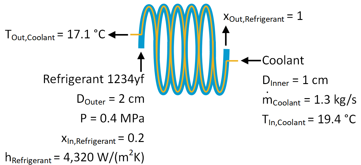
Make the following assumptions:
The evaporator is a counter flow heat exchanger.
For simplicity, assume that the evaporator contains only one tube of thermal liquid and one tube of refrigerant.
The tubes have equal lengths.
The coolant is in an inner tube with a diameter of 1 cm.
The coolant flows at a mass flow rate of 1.3 kg/s.
Coolant enters the evaporator at 19.4 degC.
Coolant leaves the evaporator at 17.1 degC.
The refrigerant is in an annular tube that encircles the inner tube. The annular tube has an outer diameter of 2 cm.
The evaporator uses refrigerant 1234yf.
The refrigerant is maintained at a pressure of 0.4 MPa.
As an idealization, assume that the evaporator is always in a state of vapor-liquid equilibrium. Refrigerant enters the evaporator with a vapor quality of 0.2 and exits the evaporator with a vapor quality of 1.
The refrigerant saturation temperature is 7.2 degC.
The refrigerant enthalpy of vaporization is 158.6 kJ/kg.
The refrigerant convective heat transfer coefficient is 4,320 W/m^2/K.
Create MATLAB variables to define the problem assumptions.
% Scenario
Tenvironment = 30; % [degC]

% Geometry
DInnerEvaporator= 0.01;  % Inner diameter [m]
DOuterEvaporator = 0.02; % Outer diameter

% Evaporator conditions
xInRefrigerant = 0.2;  % Vapor quality at inlet
xOutRefrigerant = 1; % Vapor quality at outlet

% Coolant conditions
mDotCoolant = 1.3;            % Coolant mass flow rate [Kg/s]
TInCoolantEvaporator = 19.4;  % Coolant inlet temperature [degC]
TOutCoolantEvaporator = 17.1; % Coolant outlet temperature [degC]

% Refrigerant R-1234yf properties at the evaporator pressure, 0.4 MPa
pRefrigerant = 0.4;        % Refrigerant pressure [MPa]
TRefrigerant = 7.2;        % Saturation temperature at 0.4 MPa [degC]
muSLRefrigerant = 191e-6;  % Saturated liquid dynamic viscosity at 0.4 MPa [Pa*s]
PrSLRefrigerant = 3.58;    % Saturated liquid Prandtl number at 0.4 MPa
rhoSLRefrigerant = 1153.3; % Saturated liquid density at 0.4 MPa [kg/m^3]
rhoSVRefrigerant = 22.2;   % Saturated vapor density at 0.4 MPa [kg/m^3]
kSLRefrigerant = 0.069;    % Saturated liquid thermal conductivity at 0.4 MPa [W/(m*K)]
hFGRefrigerant = 158.6;    % Enthalpy of vaporization at 0.4 MPa [kJ/kg]

% Coolant properties at 18 degC and 1 atm
cpCoolant = 3.358;    % Specific heat at constant pressure [kJ/kg/K]
muCoolant = 4.95e-3;  % Dynamic viscosity [Pa*s]
PrCoolant = 39.9;     % Prandtly number
kCoolant = 0.417;     % Thermal conductivity [W/(m*K)]
Calculate the overall heat transfer coefficient. Use the log-mean temperature difference to calculate the overall heat transfer coefficient since you know the inlet and outlet temperatures for both fluids of the counter flow heat exchanger.
The heat capacity rate for the coolant is
CCoolant = mDotCoolant * cpCoolant % [kW/K]CCoolant = 4.3654
The heat transfer is
q = CCoolant * (TInCoolantEvaporator - TOutCoolantEvaporator) % [kW]q = 10.0404
For a counter flow heat exchanger, the log-mean temperature difference is
where
is the temperature difference between the hot fluid (coolant) and cold fluid (refrigerant) at the hot fluid inlet.
is the temperature difference between the hot fluid (coolant) and cold fluid (refrigerant) at the hot fluid outlet.
deltaT1 = TInCoolantEvaporator - TRefrigerant;  % [K] Temperature difference at coolant inlet
deltaT2 = TOutCoolantEvaporator - TRefrigerant; % [K] Temperature difference at coolant outlet

deltaTlm = (deltaT2 - deltaT1) / log(deltaT2 / deltaT1); % Log mean temperature difference [K]
The overall heat transfer coefficient, , relates to the log mean temperature difference and heat transfer by
Solve for
UA = q / deltaTlm % [kW/K]UA = 0.9119
Alternatively, you can use the E-NTU method to calculate the overall heat transfer coefficient.
For the refrigerant undergoing phase change, the heat capacity rate is infinite
Where
is the refrigerant mass flow rate.
is the refrigerant specific heat at constant pressure.
CRefrigerant = inf; % [kW/K] Refrigerant heat capacity rateThe coolant has the minimum heat capacity rate
Cmin = min(CRefrigerant, CCoolant); % [kW/K]The heat capacity ratio is
.
Cmax = max(CRefrigerant, CCoolant); % [kW/K]
Cr = Cmin / Cmax
Cr = 0
The heat capacity ratio equals 0 for the evaporator with the refrigerant undergoing phase change.
The maximum heat transfer possible for a counter flow heat exchanger with the given inlet temperatures is
where is the refrigerant temperature at the evaporator inlet.
qMax = Cmin * (TInCoolantEvaporator - TRefrigerant) % [kW]qMax = 53.2579
The heat exchanger effectiveness is
.
effectiveness = q / qMax
effectiveness =
0.1885
Determine the number of transfer units. For an evaporator with a heat capacity ratio of 0, the heat exchanger number of transfer units relates to the effectiveness by
.
Use a plot to visualize the relationship of effectiveness to NTU:
effectivenessCurve = 0:0.001:0.9;
NTUcurve = -log(1 - effectivenessCurve);
figure;
plot(NTUcurve, effectivenessCurve)
xlabel('NTU');
ylabel('\epsilon')
title('Effectiveness of the Evaporator')
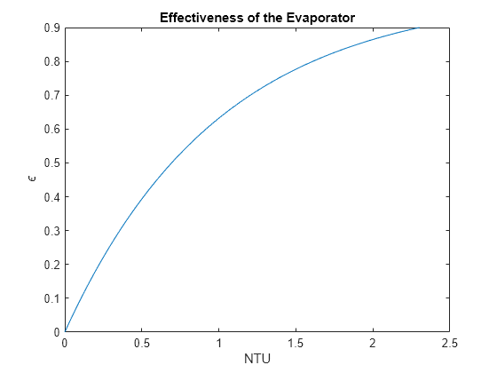
Solve for the NTU at the effectiveness point:
NTU = -log(1 - effectiveness)
NTU =
0.2089
NTU relates to the overall heat transfer coefficient by
.
Solve for .
UA = NTU * Cmin % [kW/K]UA = 0.9119
The Effectiveness-NTU (E-NTU) method and log mean temperature difference (LMTD) method predict the same overall heat transfer coefficient. The LMTD method requires fewer steps than the E-NTU method when the inlet and outlet temperatures are known (or easily calculated) and the system has a simple configuration.
Calculate the refrigerant mass flow rate.
The heat absorbed by the refrigerant is
where:
is the refrigerant enthalpy of vaporization.
is the refrigerant vapor quality at the inlet.
is the refrigerant vapor quality at the outlet.
Solve for the mass flow rate
.
mDotRefrigerant = q / (hFGRefrigerant*((xOutRefrigerant - xInRefrigerant))) % [kg/s]mDotRefrigerant = 0.0791
Confirm that the convective heat transfer coefficient for the refrigerant is 4,320 W/m^2/K.
The hydraulic diameter for heat transfer through an annular channel is
where:
is the annular channel inner diameter.
is the annular channel outer diameter.
The Reynolds number for heat transfer is
where
is the cross-sectional area of the annular channel.
is the fluid dynamic viscosity.
For the refrigerant in a state of mixed liquid-vapor, the Nusselt number follows the Cavallini-Zecchin correlation
where
and are the Reynolds number of the saturated liquid and saturated vapor, respectively.
and are Prandtl number of the saturated liquid and saturated vapor, respectively.
and are the density of the saturated liquid and saturated vapor, respectively.
The convective heat transfer coefficient for the refrigerant is
,
Where is the thermal conductivity of the saturated liquid.
The geometric factor for an annular cross-section is
Calculate the convective heat transfer coefficient for the refrigerant.
DhRefrigerant = DOuterEvaporator - DInnerEvaporator; % Annular channel [m]
SRefrigerant = pi * (DOuterEvaporator^2 - DInnerEvaporator^2) / 4; % [m^2]
ReSLRefrigerant = (mDotRefrigerant * DhRefrigerant) / (SRefrigerant * muSLRefrigerant); % [-]

% Calculate the Nusselt number
rhoFactor = sqrt(rhoSLRefrigerant/rhoSVRefrigerant) - 1;
NuRefrigerant = 0.05*ReSLRefrigerant^0.8*PrSLRefrigerant^0.33*...
    ( ( rhoFactor*xOutRefrigerant + 1 )^1.8  - ( rhoFactor*xInRefrigerant + 1 )^1.8 ) / ...
    ( 1.8*rhoFactor*(xOutRefrigerant - xInRefrigerant) );
% Convective heat transfer coefficient
fGeo = 0.86*(DOuterEvaporator/DInnerEvaporator)^0.16;
hRefrigerant = fGeo * NuRefrigerant * kSLRefrigerant / DhRefrigerant % [W/m^2/K]
hRefrigerant =
4.3202e+03
Calculate the convective heat transfer coefficient for the coolant.
The Nusselt number is
The convective heat transfer coefficient is
Where:
is the thermal conductivity.
is the hydraulic diameter.
For the coolant in a circular tube:
DhCoolant= DInnerEvaporator; % [m]
SCoolantEvaporator = pi * DInnerEvaporator^2 / 4; % [m^2]
ReCoolant = (mDotCoolant * DhCoolant) / (SCoolantEvaporator * muCoolant); % [-]
NuCoolant = 0.023*ReCoolant^0.8*PrCoolant^0.33; % [-]
hCoolantEvaporator = NuCoolant * kCoolant / DhCoolant % [W/m^2/K]
hCoolantEvaporator =
1.3477e+04
Calculate the evaporator overall heat transfer coefficient and required length.
The overall heat transfer coefficient, , relates to the fluid heat transfer coefficients by
.
The heat transfer surface area for both fluids is along the inner diameter of the annular pipe
where is the pipe length.
Rearrange the overall heat transfer coefficient equation and substitute in the surface area expression to solve for the required pipe length
Levaporator = (UA * 1000) / (pi * DInnerEvaporator) * ( 1/hRefrigerant + 1/hCoolantEvaporator) % [m]Levaporator = 8.8730
Check the Behavior in a Test Harness
Compare the calculated response to the Simscape simulated response.
open_system('EVBatteryCoolingSystemDesignEvaporatorHarness');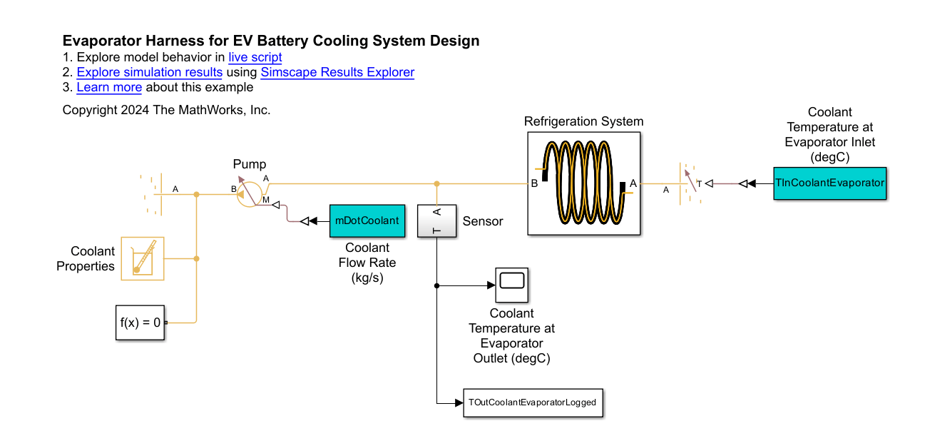
open_system('EVBatteryCoolingSystemDesignEvaporatorHarness/Refrigeration System');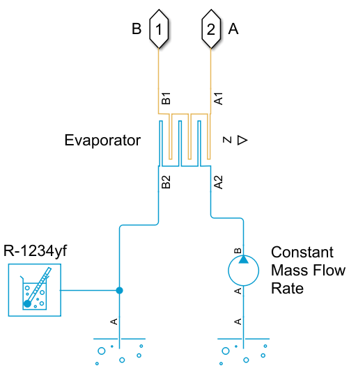
The test harness isolates the evaporator from the rest of the battery cooling system. The test harness has fixed mass flow rates and boundary conditions at the inlets and outlets for both the coolant and refrigerant.
sim('EVBatteryCoolingSystemDesignEvaporatorHarness');
TOutCoolantEvaporatorSimulated = TOutCoolantEvaporatorLogged(end) % [degC]
TOutCoolantEvaporatorSimulated =
17.0927
At the design point, the evaporator cools the coolant from 19.4 degC to 17.1 degC, as expected. The slight discrepancies between the calculated and simulated values are due to how the simulation uses fluid properties that are a function of pressure and temperature while the calculations assume the properties are constant.
Check the Behavior in the Full Model
Configure the model to direct all coolant through the evaporator. The model directs all coolant through the evaporator when the valve control signal has a value of 1. Then simulate the model.
open_system('EVBatteryCoolingSystemDesign');

valveOpeningFraction = 1;

sim('EVBatteryCoolingSystemDesign');

% Check simulated results
TBatteryLogged(end) % [degC]
ans =
19.9636
QBatteryLogged(end) % [kW]ans = 10.0568
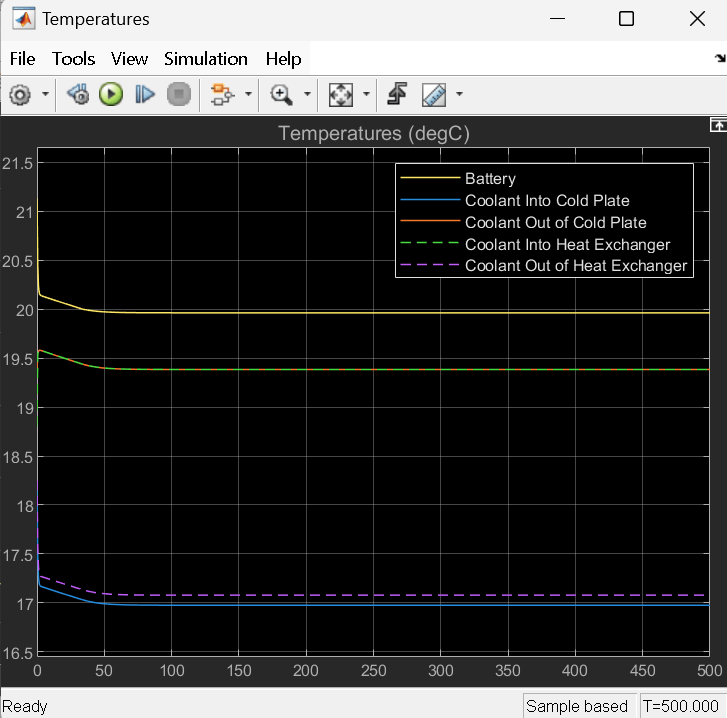
TInCoolantHXLogged(end) % Coolant temperature at evaporator inlet [degC]ans = 19.3847
TOutCoolantHXLogged(end) % Coolant temperature at evaporator outlet [degC]ans = 17.0779
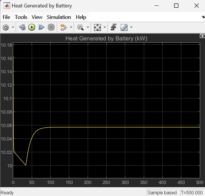
In the full model, the battery is maintained at a temperature of 20.0 degC and generates 10.1 kW heat. The evaporator cools the coolant from 19.4 degC to 17.1 degC. The temperatures in the full model slightly deviate from the temperatures in the harness due to the effects of the pump, tank, and valve in the closed loop system.
