Choose Pretrained Cellpose Model for Cell Segmentation
This example shows how to segment cells from microscopy images using a pretrained Cellpose model.
The Cellpose Library [1],[2] provides several pretrained models for cell segmentation in microscopy images. To learn more about each model and its training data, see the Models page of the Cellpose Library Documentation. In this example, you segment an image using three pretrained Cellpose models and visually compare the results. You can use this approach to find the pretrained model that is most suitable for your own images. If none of the pretrained models work well for an image data set, you can train a custom Cellpose model using transfer learning. For more information on training, see the Train Custom Cellpose Model example.
This example requires the Medical Imaging Toolbox™ Interface for Cellpose Library. You can install the Medical Imaging Toolbox Interface for Cellpose Library from Add-On Explorer. For more information about installing add-ons, see Get and Manage Add-Ons. The Medical Imaging Toolbox Interface for Cellpose Library requires Deep Learning Toolbox™ and Computer Vision Toolbox™.
Load Image
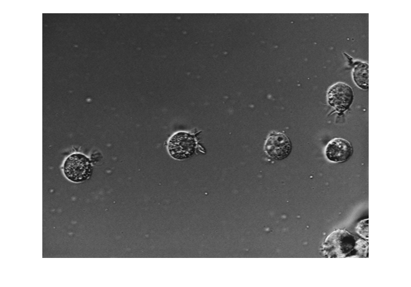
Read and display an image. This example uses a single-channel grayscale image that is small enough to fit into memory. When working with your own images, consider these tips:
Cellpose models expect a 2-D intensity image as input. If you have an RGB or multi-channel image, you can convert to grayscale by using the
im2grayfunction or extract a specific color channel by using theimsplitfunction. In general, pick the channel with the strongest edges for the cell boundary. If your image contains a separate channel for nuclear staining, consider specifying the nuclear image during segmentation using theAuxiliaryChannelname-value argument of thesegmentCells2Dfunction.If you have many images to segment, pick a representative image or subset of images. Use an image that contains cells of the type and shape you want to label in the full data set.
If you are working with large images, such as whole-slide microscopy images, extract a representative region of interest. Pick a region containing the cell types you want to label in the full image. For an example that uses the
blockedImageobject andgetRegionobject function to extract a region from a large microscopy image, see Process Blocked Images Efficiently Using Partial Images or Lower Resolutions.
img = imread("AT3_1m4_01.tif");
imshow(img)
Measure Average Cell Diameter
To ensure accurate results, specify the approximate diameter of the cells, in pixels. This example assumes a diameter of 56 pixels.
averageCellDiameter = 56;
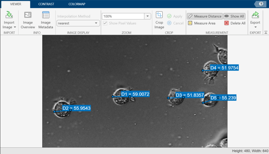
Alternatively, you can measure the approximate diameter in the Image Viewer app. Open the app by entering this command:
imageViewer(img)
In the Viewer tab of the app toolstrip, click Measure Distance. In the main display pane, click one point on the boundary of the cell you want to measure, and drag to draw a line across the cell. When you release the button, the app labels the line with a distance measurement, in pixels. You can reposition the endpoints or move the whole line by dragging the ends or middle portion of the line, respectively. This image shows an example of several distance measurements in the app.

Segment Image Using Cellpose Models
In this section, you compare the results from three of the pretrained Cellpose Library models: cyto, cyto2, and nuclei.
Configure Cellpose Models
Create a cellpose object for each model, specifying the Model property for each object. The first time you create an object for a given model, MATLAB® downloads the model from the Cellpose Library and saves a local copy. By default, MATLAB saves the models in a folder named cellposeModels within the folder returned by the userpath function. You can change the save location by specifying the ModelFolder property at object creation.
cpCyto = cellpose(Model="cyto");
cpCyto2 = cellpose(Model="cyto2");
cpNuclei = cellpose(Model="nuclei");
Predict Cell Segmentation Labels
Segment the image using each of the three models by using the segmentCells2D object function.
First, specify values for the cell threshold and flow error threshold. The cell threshold typically ranges from –6 to 6, and the flow error threshold typically ranges from 0.1 to 3. For this example, set these values so as to favor a greater number of detections.
cellThreshold = -6;
flowThreshold = 3;
Predict labels for each model. The segmentCells2D object function returns a 2-D label image, where each cell detected by the model has a different numeric pixel value.
labels1 = segmentCells2D(cpCyto,img, ...
    ImageCellDiameter=averageCellDiameter, ...
    CellThreshold=cellThreshold, ...
    FlowErrorThreshold=flowThreshold);

labels2 = segmentCells2D(cpCyto2,img, ...
    ImageCellDiameter=averageCellDiameter, ...
    CellThreshold=cellThreshold, ...
    FlowErrorThreshold=flowThreshold);

labels3 = segmentCells2D(cpNuclei,img, ...
    ImageCellDiameter=averageCellDiameter, ...
    CellThreshold=cellThreshold, ...
    FlowErrorThreshold=flowThreshold);
Compare Results
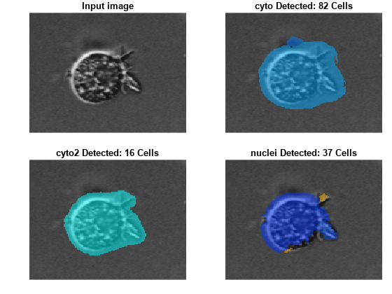
Visualize the input image and the results from each model. The title for each image includes the model name and the number of cells detected.
figure
tiledlayout(2,2,TileSpacing="tight",Padding="tight")

nexttile
h1 = imshow(img);
title("Input image")
nexttile
h2 = imshow(labeloverlay(img,labels1));
nl = numel(unique(labels1(:))) - 1;
title(cpCyto.Model + " Detected: " + nl + " Cells")
nexttile
h3 = imshow(labeloverlay(img,labels2));
nl = numel(unique(labels2(:))) - 1;
title(cpCyto2.Model + " Detected: " + nl + " Cells")
nexttile
h4 = imshow(labeloverlay(img,labels3));
nl = numel(unique(labels3(:))) - 1;
title(cpNuclei.Model + " Detected: " + nl + " Cells")

linkaxes([h1.Parent h2.Parent h3.Parent h4.Parent])

Zoom in each image to compare the results from each model for a single cell. In general, you want to select a model that accurately detects the correct number of cells, such that it detects one real cell as one cell in the label image. Based on the zoomed in image, the cyto2 model is most suitable for this family of images.
xlim([200 370])
ylim([190 320])

Once you have selected a model, you can refine the accuracy of the boundaries by tuning parameters such as the cell threshold and flow error threshold. For more information, see the Refine Cellpose Segmentation by Tuning Model Parameters example.
References
[1] Stringer, Carsen, Tim Wang, Michalis Michaelos, and Marius Pachitariu. “Cellpose: A Generalist Algorithm for Cellular Segmentation.” Nature Methods 18, no. 1 (January 2021): 100–106. https://doi.org/10.1038/s41592-020-01018-x.
[2] Pachitariu, Marius, and Carsen Stringer. “Cellpose 2.0: How to Train Your Own Model.” Nature Methods 19, no. 12 (December 2022): 1634–41. https://doi.org/10.1038/s41592-022-01663-4.
See Also
cellpose | segmentCells2D | trainCellpose | segmentCells3D | downloadCellposeModels
Topics
- Refine Cellpose Segmentation by Tuning Model Parameters
- Train Custom Cellpose Model
- Detect Nuclei in Large Whole Slide Images Using Cellpose