AC Metrics of Fourth Order Delta Sigma ADC
This example shows how to model a fourth order delta sigma ADC and measure its AC metrics. The ADC AC Measurement block from the Mixed-Signal Blockset™ is used to measure the AC performance of the ADC. AC measurements are essential to measure the metrics like SNR and ENOB inform the designer whether optimal performance is being achieved by the design. If not, the designer can tweak the design parameters to make the better.
Fourth Order Delta Sigma ADC
This ADC model shows a behavioral model of a delta sigma ADC that uses a 4th order modulator. The ADC input sample rate is 1.024 MHz. After decimation filter, the output sample rate is 8 kHz. The ADC model and testbench is modeled entirely in discrete-time.

model = 'MSADCFourthOrderDeltaSigma';
open_system(model)
sim(model);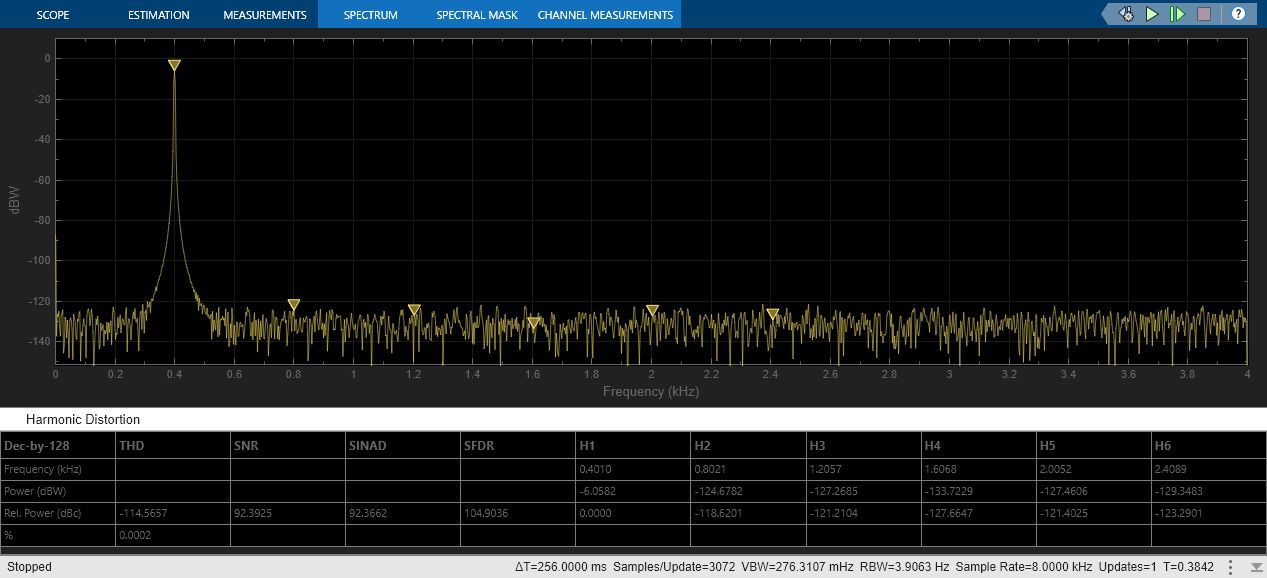

Use a single-tone sine wave to test the ADC, where the input frequency is set via a discrete-time voltage controlled oscillator (VCO). You can use the slider gains Freq in Hz and Peak Signal Amplitude to change the characteristics of the input signal while the simulation is running.
You can view the ADC output in the time-domain by comparing the result against an ideal converter. The output of the ADC is also visualized in the frequency-domain. You can activate the measurements capability of the spectrum analyzer block to compute distortion metrics such as THD, SNR, and SFDR.
ADC AC Measurement Block
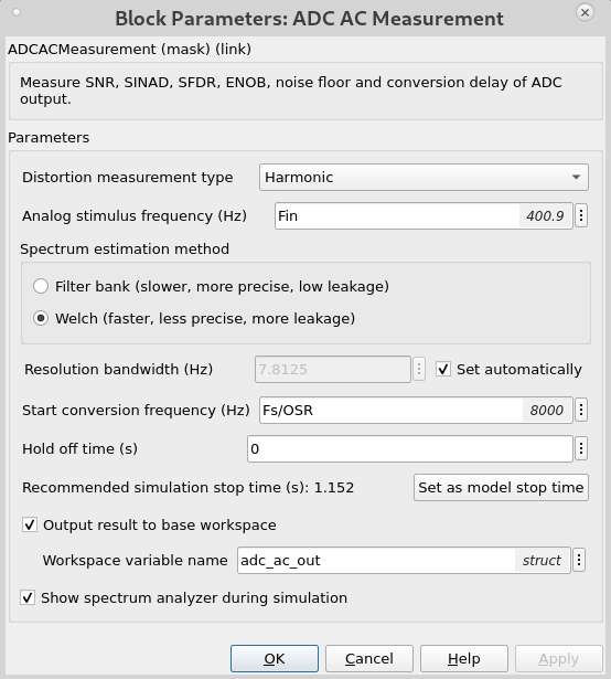
In addition, ADC metrics like SINAD, ENOB, etc. can be measured using the ADC AC Measurement block from MSB. The mask settings used for this testcase are shown below.
Modulator Architecture
The modulator block implements a discrete-time behavioral 4th order modulator [1]. The modulator has both feed-forward and feedback paths. The modulator parameters are specified by MATLAB® variables defined in the model initialization call back:
Integrator gains:
a1 = 1/3;
a2 = 3/25;
a3 = 1/10;
a4 = 1/25;
Feedforward gains:
b1 = 1;
b2 = 0.8;
Feedback gains
alpha=1/5;
beta=1/2;
Inspect the modulator subsystem:

Decimation Filter
The modulator output drives a multi-rate discrete-time low pass filter that uses a Cascade Integrator Comb (CIC) filter for a data rate reduction by 16.
The following FIR filter further reduces the rate by a factor of 8 and is designed to have an inverse sinc roll-up in the passband to compensate for the droop in the CIC stage. This can be seen by clicking on 'View Filter Response'.

The decimating filter subsystem contains a mixture of floating and fixed-point implementations. The CIC filter must be implemented in fixed-point. The polyphase filter is implemented in both 16 bit fixed-point and double-precision floating point for comparison purposes.

Required Products
This example requires:
MATLAB
Simulink®
Signal Processing Toolbox™
DSP System Toolbox™
Fixed-Point Designer™
References
M. Yavari, O. Shoaei, A. Afzali-Kusha, "A very low-voltage, low-power power and high-resolution sigma delta modulator for digital audio in 0.2Sum CMOS", proceedings of 2003 IEEE International Symposium on Circuits and Systems (ISCAS).
______________________________________________________________________________
Select a Web Site
Choose a web site to get translated content where available and see local events and offers. Based on your location, we recommend that you select: United States.
You can also select a web site from the following list
Americas
- América Latina (Español)
- Canada (English)
- United States (English)
Europe
- Belgium (English)
- Denmark (English)
- Deutschland (Deutsch)
- España (Español)
- Finland (English)
- France (Français)
- Ireland (English)
- Italia (Italiano)
- Luxembourg (English)
- Netherlands (English)
- Norway (English)
- Österreich (Deutsch)
- Portugal (English)
- Sweden (English)
- Switzerland
- United Kingdom (English)
Asia Pacific
- Australia (English)
- India (English)
- New Zealand (English)
- 中国
- 日本Japanese (日本語)
- 한국Korean (한국어)