Simulink PLC Coder Workflow vs. Rockwell Automation RSLogix IDE Workflow
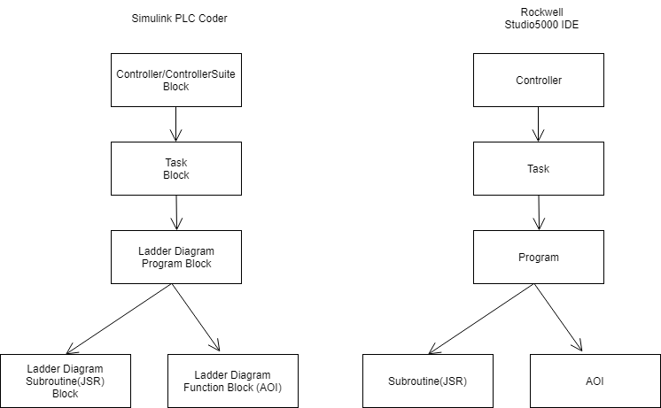
These flowcharts show the workflow comparison in a ladder diagram created by Simulink® PLC Coder™ versus a ladder diagram created in the Rockwell Automation® RSLogix™ IDE.
You first place either the PLC Controller or PLC Controller Suite block onto the blank Simulink model page. This block contains all the tasks, programs, program tags, controller tags, routines, AOI blocks and so on. For more information, see PLC Controller.
You place the Task block inside the PLC Controller or PLC Controller suite block. The Task blocks house the programs, program tags, routines, AOI blocks, and so on. For more information see, Task.
You place the Ladder Diagram Program block or blocks inside the Task block. The Ladder Diagram Program block contains program tags, routines , AOI blocks, and so on. For more information see, Program
You next place JSR (Jump To Subroutine) blocks within the Ladder Diagram Program block. The JSR blocks contain the ladder rungs, ladder logic and AOI blocks within them. For more information see ,Subroutine.
You can place the AOI block either inside the JSR block or inside the Ladder Diagram Program block. For more information see, Function Block (AOI).
See Also
PLC Controller | PLC Controller
Suite | Task | Program | Subroutine | Function Block
(AOI)