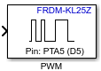
PWM Output
Generate square wave on the specified output pin
Add-On Required: This feature requires the Simulink Coder Support Package for NXP FRDM-KL25Z Board add-on.
Libraries:
Simulink Coder Support Package for NXP FRDM-KL25Z
Board/FRDM-KL25Z
Description
Add-On Required: This feature requires the Simulink Coder Support Package for NXP FRDM-KL25Z Board add-on.
The PWM Output block generates square-wave pulses
and outputs to the specified pin on the board. You can provide a value
between 0–100 as the block input. The input value that you
provide controls the duty cycle of the pulse waveform. An input value
of 0 produces a 0% duty cycle and an input value
of 100 produces a 100% duty cycle.
Ports
Input
Parameters
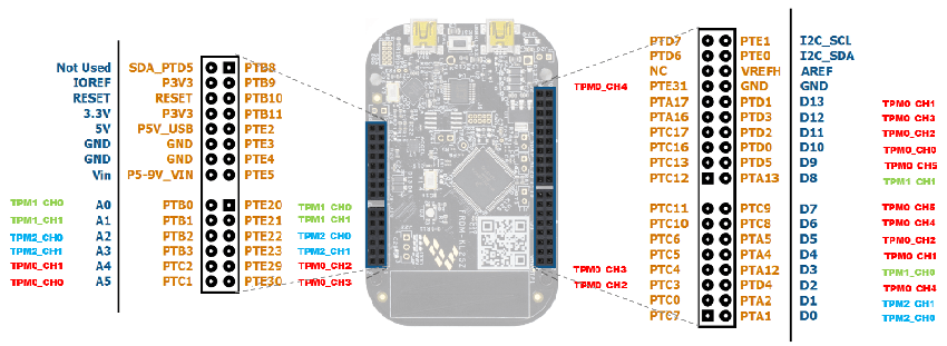
To view the pin mapping on the board, click View Pin Map. On the board, each PWM pin is connected to either of the three timers, TPM0 (Timer PWM Module), TPM1, or TPM2. To learn about the Timer Channel Pin combination, see the Timer to Pin Mapping table in the Timer/PWM module parameter description section.
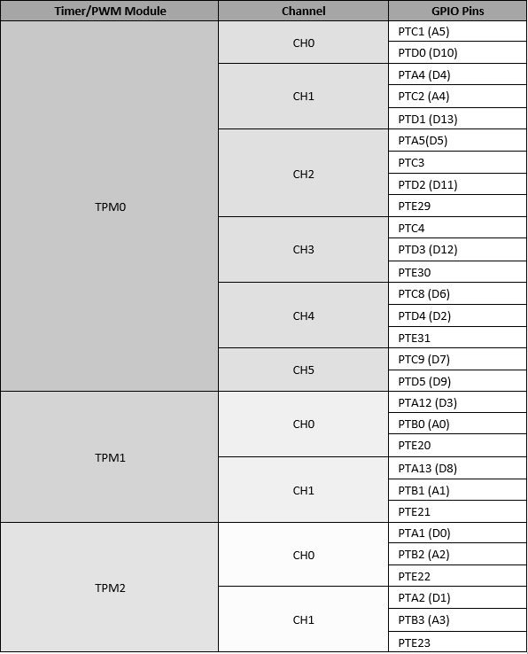
The board has three timers, TPM0, TPM1, and TPM2. Each PWM pin
is connected to one of these three timers. When you select a pin in
the Pin list, this parameter is populated with
the timer to which the pin is connected. For example, if you select
the PTA1 (D0) pin, this parameter is set
to TPM2.
The following table shows timer to pin mapping.
In your model, if you have more than one instance of the PWM Output block, use a different Timer Channel combination for every block instance. Otherwise, you receive an error message indicating you to use GPIO Pins from different Timer Channel combination for all the block instances.
For example, suppose that in one PWM Output block
instance you select the PTC3 pin to generate
the output. The PTC3 pin is connected to
the CH2 channel of the TPM0 timer. When selecting a pin for the other
instances of the PWM Output block, select a pin that
belongs to a timer channel combination other than TPM0 CH2.
Dependencies
This parameter appears dimmed.
When initializing, the block sets its duty cycle to the value that you specify in this parameter.
Example
This example shows how to use the PWM Output block
to control the brightness of the blue LED connected to the D13 pin
on the board.
Connect the FRDM-KL25Z hardware to your computer.
In the Simulink® Editor, open a new model window. From the Library Browser, copy a Constant block and a PWM Output block and connect them.
Set the value of the Constant block to
50. This value represents the duty cycle of the output square wave in percentage.In the Block Parameter dialog box, set the Pin to
D13and the Initial duty cycle to0.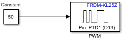
In the Simulink Editor, select Simulation > Model Configuration Parameters.
In the Configuration Parameters dialog box, click Hardware Implementation.
Set the Hardware board parameter to NXP FRDM-KL25Z.
To set the frequency of the output signal, identify the timer to which the
D13pin is connected.To identify the timer, in the Block Parameter dialog box, click View Pin Map. In the pin map, search for the
D13pin and the timer name next to it. TheD13pin is connected to theTMP0pin.In the Configuration Parameters dialog box, set the TPM0 Frequency (in Hz) to
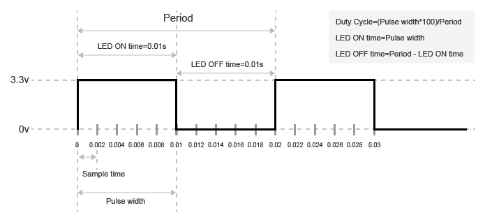
50. Using the frequency value, the block calculates the period of the square wave.Period = 1/50 = 0.02 seconds
When you build the model and load it on the hardware, the PWM Output block generates square-wave pulses with the pulse width of (50* 0.02)/100 = 0.01 seconds. The blue LED turns on for 0.01 seconds, and then it turns off for the next 0.01 seconds. You can blink an LED on and off quickly to control its brightness with the PWM Output block.
Version History
Introduced in R2016b
See Also
Digital Output | Digital Input | Analog Output | Analog Input