Create Real-Time Applications Using Variants and Simulink Real-Time
This example shows you how to create a real-time application with a variant subsystem by using the Simulink® Real-Time™ workflow. Simulink Real-Time lets you create real-time applications from Simulink models and run them on Speedgoat® target computer hardware connected to your physical system.
To run a Simulink Real-Time model on a target computer, connect the development and target computers in a network. For the steps, see Set Up and Configure Simulink Real-Time (Simulink Real-Time).
Explore and Set Up Model
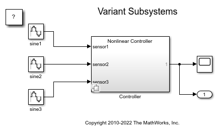
Open the model sldemo_variant_subsystems. The model contains a variant subsystem block Controller with two choices, Linear Controller and Nonlinear Controller, and has the conditions VSS_MODE == 1 and VSS_MODE == 2 respectively.
To create a real-time application:
1 In the Block Parameters dialog box, set the Variant activation time to startup.
2 Check that the Variant control expression is set to VSS_MODE == 1 for Linear Controller* or VSS_MODE == 2 for Nonlinear Controller.
3 Create the variant parameter VSS_MODE as a Simulink.Parameter with a value of 1 and data type of int32.
VSS_MODE = Simulink.Parameter(int32(1));
4 Set the storage class of VSS_MODE to ExportedGlobal.
VSS_MODE.CoderInfo.StorageClass = 'ExportedGlobal';
5 Change the variant choices to atomic.
open_system('sldemo_variant_subsystems');
To provide information to Simulink Coder on how to build a real-time application from the model, set the simulation and real-time run parameters in the Configuration Parameters dialog box. To open the Configuration Parameters dialog box, on the Modeling tab, click Model Settings.
1 On the Solver pane, under Solver selection, from the Type list, select Fixed-step.
2 On the Code Generation pane, in the Target selection section, from the System target file list, select an STF for a Simulink Real-Time model.This selection is required to build a real-time application.
3 In the Optimization pane, select the Default parameter behaviour to Tunable.
4 On the Interface pane, under the Data exchange interface, clear the External mode check box.
The model is now ready to be used to build a standalone real-time application using the current configuration parameter settings.
Create and Run Real-Time Application
Create the real-time application using the slbuild command. This generates the real-time application MLDATX file.
slbuild('sldemo_variant_subsystems');
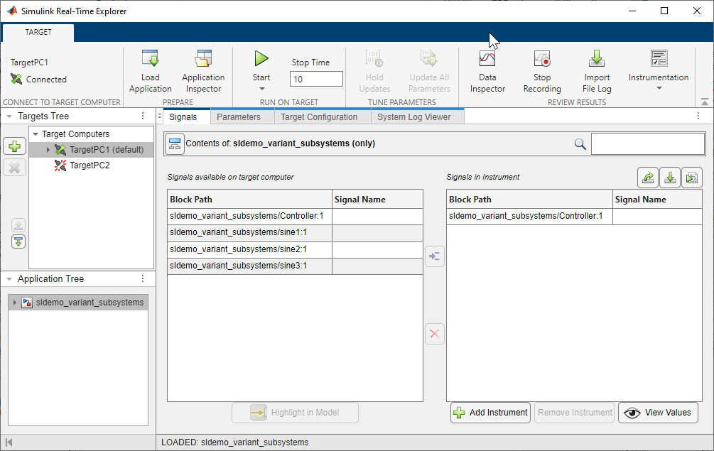
Open the Simulink Real-Time Explorer, using the slrtExplorer (Simulink Real-Time) command.
slrtExplorer
Load the real-time application sldemo_variant_subsystems.mldatx by clicking Load Application. In slrtExplorer, you can:
1 View a hierarchical display of signals in the Signals tab. You can see all the signals available under Signals available on target computer. Select the signal that you want to observe and add it to Signals in Instrument.
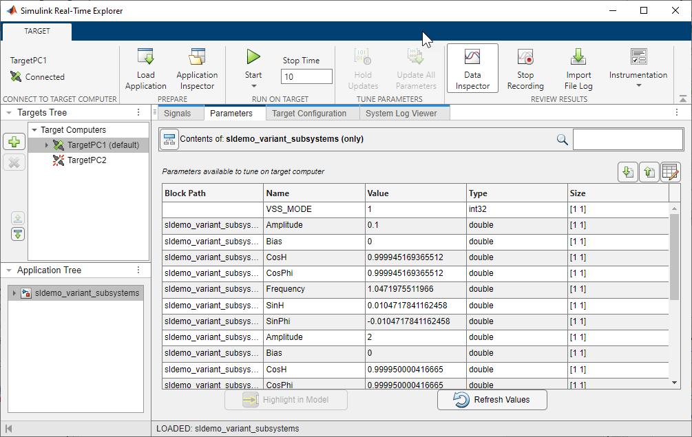
2 Tune parameters in the Parameters tab. The value of the variant control variable VSS_MODE is set to 2 by default, as this was the value specified at compile-time. Before starting the simulation, you can choose to change the value to 1. This variable is set back to the default value at the end of the simulation.
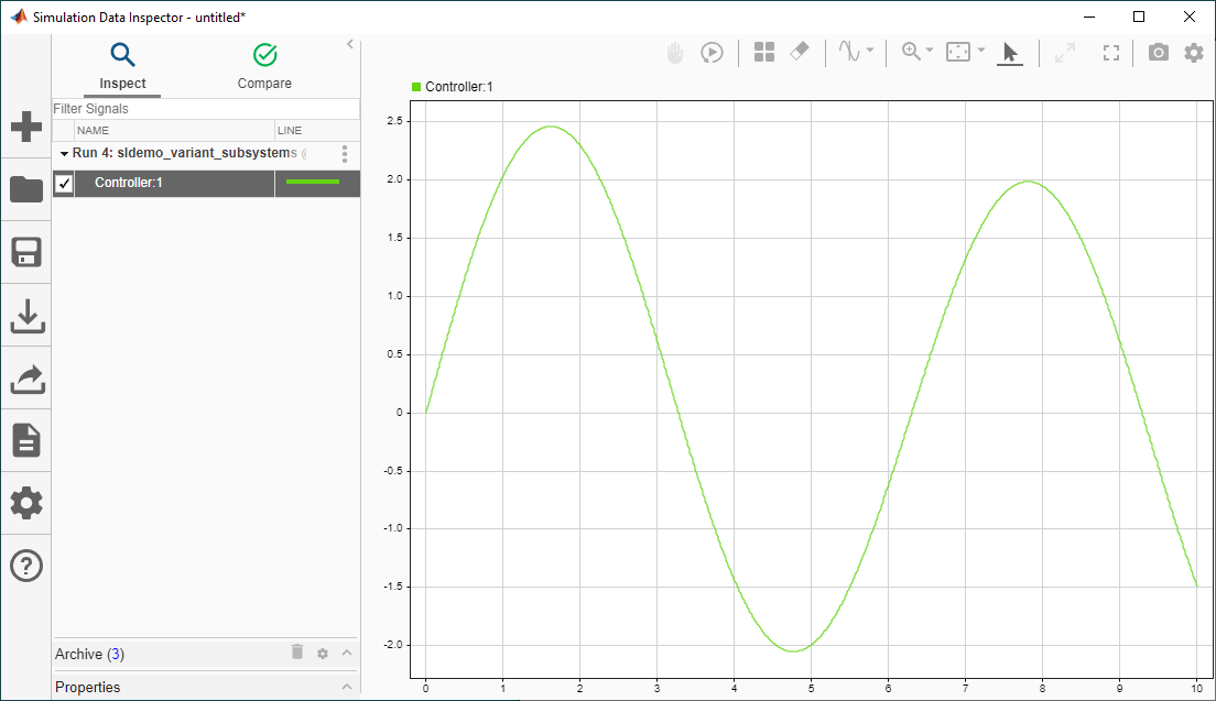
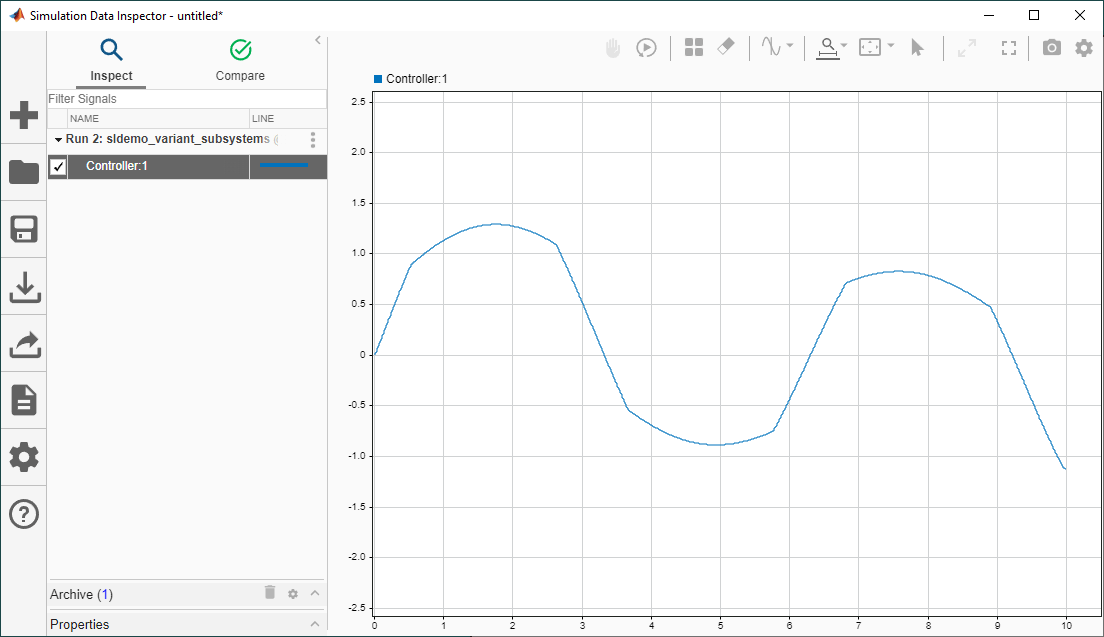
3 Stream data to the Simulation Data Inspector. Run the real-time simulation. Open the Simulation Data Inspector and observe the different results for VSS_MODE == 1 and VSS_MODE == 2.
NOTE: Check that you do not change the variant control value VSS_MODE while the simulation is running. Simulink does not issue an error in case you change the variant control in between steps.
Output when VSS_MODE == 1
Output when VSS_MODE == 2
See Also
Activate Variant During Different Stages of Simulation and Code Generation Workflow
Create and Run Real-Time Application from Simulink Model (Simulink Real-Time)
Simulink Real-Time Explorer (Simulink Real-Time)
You can also select a web site from the following list:
Americas
- América Latina (Español)
- Canada (English)
- United States (English)
Europe
- Belgium (English)
- Denmark (English)
- Deutschland (Deutsch)
- España (Español)
- Finland (English)
- France (Français)
- Ireland (English)
- Italia (Italiano)
- Luxembourg (English)
- Netherlands (English)
- Norway (English)
- Österreich (Deutsch)
- Portugal (English)
- Sweden (English)
- Switzerland
- United Kingdom (English)