Display Bus Information
When you use buses in your model, you can display bus information using multiple approaches.
For example:
To identify buses in your block diagram, use their compiled line styles.
To view bus hierarchy, use the Signal Hierarchy Viewer.
To trace bus elements to their source or destination, use the Signal Hierarchy Viewer.
To view simulation data for buses, use port value labels to display bus element values in the block diagram or use the Simulation Data Inspector.
To get bus information programmatically, use the
get_paramfunction.
Display Bus Line Styles
To visually identify buses after model compilation, use line styles.
| Line Type | Line Style |
|---|---|
| Virtual bus | |
| Nonvirtual bus | |
| Array of buses |
To compile a model, in the Simulink® Toolstrip, on the Modeling tab, click Update Model or Run.
View Bus Hierarchy
To display bus hierarchy:
Select a bus in your model.
In the Simulink Toolstrip, on the Signal tab, click Signal Hierarchy.
A Signal Hierarchy Viewer opens, showing the signal hierarchy for the selected bus.
For example, this Signal Hierarchy Viewer shows the signal hierarchy for a bus
named main_bus.
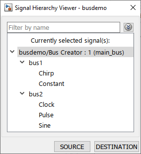
The Signal Hierarchy Viewer displays the hierarchy for the currently selected bus. If you select a different bus, the Signal Hierarchy Viewer updates to show the selected bus. If you edit a bus, the Signal Hierarchy Viewer reflects those updates.
For more information and an example, see Signal Hierarchy Viewer.
Trace Bus Element to Source or Destination
To trace a bus element to its source or destination using the Signal Hierarchy Viewer:
Select a bus in your model.
In the Simulink Toolstrip, on the Signal tab, click Signal Hierarchy.
The Signal Hierarchy Viewer opens, showing the signal hierarchy for the selected bus.
In the Signal Hierarchy Viewer, select the element name.
In the Signal Hierarchy Viewer, click Source or Destination to highlight source blocks or destination blocks, respectively.
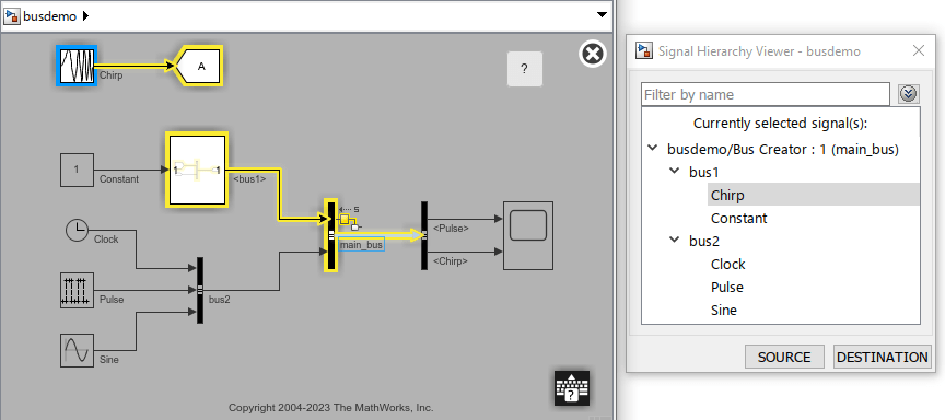
For example, this block diagram view highlights the path to all source blocks for a bus
element named Chirp from a bus named
main_bus.
To trace a signal with the Signal Hierarchy Viewer, you must have at least one signal line selected.
For more information and examples, see Signal Hierarchy Viewer.
Display Bus Element Values
To display the values of bus elements in the block diagram, use port value labels.
Select a bus in your model.
On the Signal tab, select Output Value Label.
Click the port value label. Then, select the bus elements for which you want to display values.
For example, in the example model named busdemo, suppose you select all nonconstant signals in the bus named main_bus.
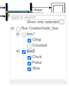
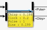
When you simulate the model, the port value label shows the names and values of the signals you selected.
For more information, see View Signal Values Using Port Value Labels.
View Simulation Data for Buses
When you view simulation data for buses, you plot the data for leaf elements of the buses.
Open and simulate the model named BasicModelingBuses.
mdl = "BasicModelingBuses";
open_system(mdl);
sim(mdl);
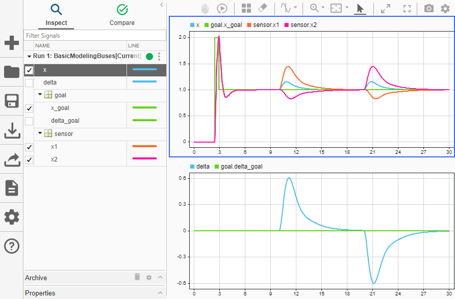
This model logs data for the buses named goal and sensor.
To view the data logged in the simulation, in the Simulink Toolstrip, on the Simulation tab, click Data Inspector.
By default, the Simulation Data Inspector groups signals by data hierarchy. For buses, the data hierarchy is the bus hierarchy.
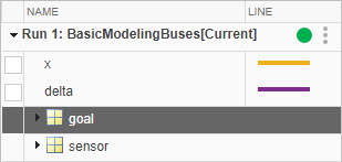
Grouping bus data based on the bus hierarchy allows you to collapse the contents of a parent bus that contains many elements. You can plot the data for leaf elements in the buses. Optionally, change the line colors.
For more information and visualization options, see Decide How to Visualize Simulation Data.
Get Bus Hierarchy and Virtuality Programmatically
To programmatically get the hierarchy and virtuality of a bus in a compiled model, query these parameters using the get_param function:
SignalHierarchy— If the signal is a bus, returns the name and hierarchy of the signals in the bus.CompiledBusType— For a model that has run the"compile"phase, returns information about whether the signal connected to a port is a bus and whether the signal is a virtual or nonvirtual bus. Before you query theCompiledBusTypeparameter value, use the model name programmatic interface to compile the model. For more information, see Use Model Name as Programmatic Interface.
Open the example. Then, open and compile the model named busdemo. Compiling the model updates the line styles, which you can use to visually identify buses.
mdl = "busdemo";
open_system(mdl)
set_param(mdl,SimulationCommand="Update");

Obtain the handle of the port for which you want bus information.
ph = get_param("busdemo/Bus Creator","PortHandles");
Get the signal hierarchy at the port.
sh = get_param(ph.Outport,"SignalHierarchy")sh = struct with fields:
SignalName: 'main_bus'
BusObject: ''
Children: [2×1 struct]
Get the compiled bus type at the port.
busdemo([],[],[],"compile");
bt = get_param(ph.Outport,"CompiledBusType")
bt =
'VIRTUAL_BUS'
Terminate the simulation that was started by compiling the model.
busdemo([],[],[],"term");Get Bus Attributes at Interfaces Programmatically
To get the attributes of a bus at a bus element port programmatically, use the get_param function.
Open the example. Then, open and compile the model named SpecifiedBusInterface. Compiling the model updates the line styles, which you can use to visually identify buses.
model = "SpecifiedBusInterface";
open_system(model);
set_param(model,SimulationCommand="Update");
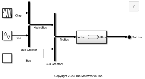
The model creates a bus named TopBus that contains a bus named NestedBus and a signal named Step. The nested bus contains signals named Chirp and Sine. The top-level bus connects to the input port of a subsystem. At the output port of the subsystem, the output bus connects to an Out Bus Element block.
Get the data type of the output bus at the root level of the model.
elem0 = "SpecifiedBusInterface/OutBus";
get_param(elem0,"OutDataTypeStr")
ans =
'Inherit: auto'
Open the subsystem, which contains In Bus Element and Out Bus Element blocks.
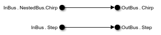
Get the minimum and maximum values of the input and output elements named Chirp. The input element named Chirp is in a nested bus in the top-level bus.
elem1 = "SpecifiedBusInterface/Subsystem/InBus.NestedBus.Chirp";
get_param(elem1,'Minimum')
ans =
'-1'
get_param(elem1,'Maximum')ans = '1'
The output element named Chirp is in the top-level bus. The output bus has no nested buses.
elem2 = "SpecifiedBusInterface/Subsystem/OutBus.Chirp";
get_param(elem2,"Minimum")
ans =
'-1'
get_param(elem2,"Maximum")ans = '1'
For more information about bus attributes at bus element ports, see In Bus Element and Out Bus Element.
See Also
Signal Hierarchy Viewer | Simulation Data Inspector