Generate ENI Files for EtherCAT Devices
This example shows how to generate EtherCAT® network information (ENI) files to use in Simulink® Real-Time™ with EtherCAT devices.
The example shows the generation process steps in EtherCAT Configurator and the process steps in the TwinCAT® XAE plugin for Microsoft® Visual Studio®.
The hardware connections are:
EK1100 -- EtherCAT coupler
EL3062 -- EtherCAT terminal
EL4002 -- EtherCAT terminal
EL9011 -- Bus End terminal
The EK1100 coupler connects EtherCAT with the EtherCAT terminals (ELxxxx). One station consists of an EK1100 coupler, any number of EtherCAT terminals, and a bus end terminal.
To provide power connections, connect the 24 V and 0 V terminals of the EK1100 to a 24 V regulated power supply (RPS) +Ve and -Ve terminals.
The EL3062 analog input terminal processes signals in the range of [-10, 10] V.
The EL4002 analog output terminal generates signals in the range of [0, 10] V.
To configure the EtherCAT network, connect the EtherCAT devices to the development computer on which the EtherCAT configurator is running. This connection permits scanning and discovery of the EtherCAT devices. After the configurator generates the XML file, you can reconnect the EtherCAT devices to the target computer. This diagram shows the suggested connections.
Install TwinCAT 3.1 XAE and Run Microsoft Visual Studio with TwinCAT
The latest version of TwinCAT is the 3.x version and that is the preferred configuration tool.
The XAE sub version does not contain the full run time engine that runs on Windows®. This is available free of charge from the Beckhoff® web site. For use with Simulink Real-Time, you do not need the run time engine because you are using the run time implementation on the target. The full version with run time engine requires the purchase of a license from Beckhoff.
The TwinCAT 3.1 software requires a supported version of Microsoft Visual Studio to be installed. TwinCAT 3.1 uses the MSVC GUI integration and does not have a GUI by itself. The versions of MSVC with which a given version of TwinCAT works are discussed in the TwinCAT documentation. Installation finds supported MSVC versions on your machine and installs to them.
To install the TwinCAT 3.1 XAE:
Go to www.beckhoff.com and select Download.
Select TwinCAT 3 and download the setup.
Install TwinCAT 3.
Start Microsoft Visual Studio.
From the TwinCAT menu, select Show Realtime Ethernet Compatible Devices.
Select the Ethernet adapter for your EtherCAT device, then select Install.
Because TwinCAT installs an Ethernet filter inline with the Ethernet port you have selected, it is good practice to add an extra Ethernet port to use exclusively with EtherCAT to avoid any possible problem the filter can cause when sharing the Simulink Real-Time host-target communication port with TwinCAT.
All EtherCAT configuration programs use EtherCAT Subordinate Information (ESI) files to describe the subordinate devices that are found on the network. These Beckhoff configuration programs come prepopulated with mostly Beckhoff devices. To correctly configure an EtherCAT network with devices from other manufacturers, you may need to get the correct ESI file from the device manufacturer web site. If you do not have an ESI file for a subordinate device on your network, the scan process does not populate the Solution Explorer with the correct name of the device and the read and write variables are not correct.
To create a new TwinCAT project in Visual Studio:
Start Visual Studio. Go to File > New > Project.
Under Installed, select TwinCAT Projects and click OK.
Verify whether the project has been created successfully in the status bar of Microsoft Visual Studio.
Enter your license if this instance is the first time that you are using TwinCAT and you installed the full version. If you are using TwinCAT in evaluation mode, fill in the Captcha.
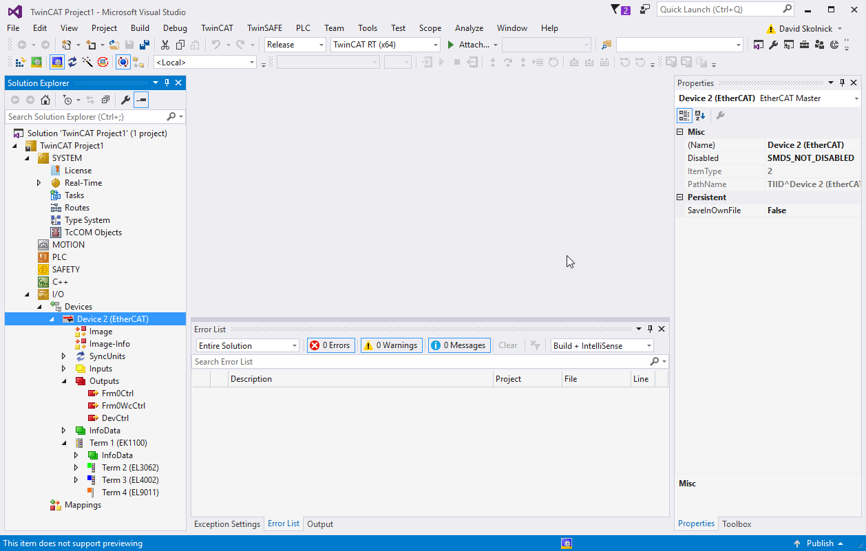
Observe the Solution Explorer pane the left side of Visual Studio.
Go to TWINCAT in the menu and select Scan. You can also right click Solution Explorer > your TwinCAT project > I/O > Devices > Scan.
A dialog box opens with the message All devices may not automatically be found. Click OK and wait for the scan to complete. You now see a dialog box saying New I/O devices have been found.
Ensure that the check box is selected, then click OK. A dialog box appears with a Scan for boxes? message. Click Yes. The EtherCAT devices in your network are scanned, and the devices appear.
You see a dialog box that asks whether to activate free run mode. Select No.
Observe the Solution Explorer and verify that the devices were scanned correctly.
When you first start TwinCAT the right information panel is not displayed. You need to double-click any item in the tree view the first time. After that the information dialog for any item is displayed by a single click on that item in the Solution Explorer tree view.
Configure EtherCAT Main Node Data with TwinCAT
To configure the EtherCAT main node, create and configure a task, then add the inputs and outputs to the task.
To create an EtherCAT Task:
In the Solution Explorer, right-click the Tasks node and select Add New Item.
In the Insert Task dialog box, select TwinCAT Task With Image, provide a name for the task, and click OK.
Select the task that you created. The value Cycle Ticks determines the cycle time as a multiple of the Base Time determined on the Real-Time item. The default task time is set to 10 ms. If you are using Distributed Clock synchronization, a task time of 1-2 ms is the slowest that works with Main Shift DC mode.
Create at least one cyclic input/output task. Link this task to at least one input variable and one output variable on each subordinate device.
If you want to run faster than 1ms time, you need to change the base time on the Real-Time item above Tasks. On the Settings tab, you need to change the Base Time selection to a faster one.
By using distributed clocks (DC), the EtherCAT protocol can synchronize the time in all local bus devices within a narrow tolerance range. Only some EtherCAT devices support DC. It is important that if a device supports DC, you configure it accordingly. For example, in the example configuration, the EL4002 supports DC. Most motion controllers (motor drives) support DC and some require it to get to Op state.
To configure EtherCAT DC:
Enable DC and choose Bus shift or Main shift DC mode.
Click on the Device n (EtherCAT) node
Select the EtherCAT tab in the information panel.
Click on Advanced Settings which opens a new dialog.
In the Advanced Settings dialog, select the Distributed Clocks page.
By default the Automatic DC Mode Selection box is checked, which generally gets you Main Shift DC mode. The first DC enabled subordinate device is the reference clock and the Simulink Real-Time execution time is shifted slightly to align execution with the reference clock.
Deselect the Automatic mode and you have control over which DC mode to use or to turn it off. Next items are with Automatic deselected.
With DC in use deselected, no Distributed clock synchronization takes place. This results in much quicker initialization time to get to Op state, but there is no synchronization between subordinate devices.
With DC in use selected, you have two different synchronization methods between the Speedgoat® target machine and the EtherCAT subordinate devices.
Independent DC Time uses the first DC enabled subordinate device as the reference clock and the target machine clock is adjusted slightly to phase lock model execution to the first DC enabled subordinate device.
DC Time controlled by TwinCAT Time should be read as controlled by target machine time in Simulink Real-Time. This is bus shift mode where the target machine is the reference clock and the subordinate device execution times are shifted slightly to phase lock to the target machine.
Select both Continuous Run-Time Measuring and Sync Window Monitoring.
Now that you have chosen the DC mode to use, you can visit all of the DC enabled subordinate devices in your network and set them to the correct mode. This example ENI file only supports one DC enabled subordinate device, the EL4002.
Click the node Term 3 (EL4002) and select the DC tab.
By default, the Operation Mode is set to SM-Synchron which does not synchronize output to DC time. Change the Operation Mode to DC-Synchron. Different subordinate devices have different names for the operating mode.
Click Advanced Settings and set the Distributed Clock options as shown.

To export and save the EtherCAT configuration, generate the ENI file:
Click the node for your EtherCAT device and click the EtherCAT tab.
Click Export Configuration File.
In the Save As dialog box, enter an XML file name, such as
simple_adda_eni.xml, then click Save. This XML file is the ENI file. The ENI file and the Simulink Real-Time model that uses the ENI file cannot have the same name. They must have different names.When you close the TwinCAT project, the editable version of this configuration is saved in the project file. You can modify the configuration by opening this project and by exporting to XML again.
Import a Device with the Configurator
Device import is often part of the workflow for third-party (different manufacturer) devices. Use this process to configure a device that is not present in the Beckhoff system. Numerous motors and their drives fall under this category. Sometimes, you must configure a device that is not present in the Beckhoff system. The TwinCAT EtherCAT main device or System Manager uses the device description files for the devices to generate the configuration in online or offline mode.
The device descriptions are contained in ESI files (EtherCAT Subordinate Information) in XML format. These files can be requested from the respective manufacturer and are made available for download. An XML file can contain several device descriptions.
The ESI files for Beckhoff EtherCAT devices are available on the Beckhoff website and are stored in the TwinCAT installation folder. The default for TwinCAT2 is C:\TwinCAT\IO\EtherCAT. The files are read (once) when you open a new System Manager window and if they have changed since the last time that you opened the System Manager window.
If using a TwinCAT configurator, the TwinCAT installation includes the set of Beckhoff ESI files which were current at the time when the TwinCAT build was created. For TwinCAT 2.11, TwinCAT 3, and later, you can update the ESI folder from the System Manager if the programming PC is connected to the Internet (Option > Update EtherCAT Device Descriptions).