AC Cable (Three-Phase)
Three-phase AC power cable
Libraries:
Simscape /
Electrical /
Passive /
Lines
Description
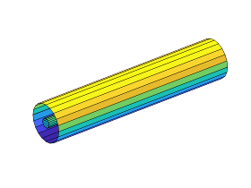
The AC Cable (Three-Phase) block represents a three-phase AC power cable with a conducting sheath surrounding each phase. The figure shows a single-phase conductor inside a conducting sheath. The inner cylinder represents the main conductor for the phase, and the outer cylinder represents the conducting sheath.
You can model composite or expanded three-phase ports by setting the Modeling option parameter to either:
Composite three-phase ports— Contains three-phase connection ports for the sheaths and phases and a single-phase connection port for each electrical reference node.Expanded three-phase ports— Contains single-phase connection ports for each sheath, phase, and electrical reference node.
The AC Cable (Three-Phase) block includes inductances and mutual inductances between each phase, sheath, and return path. Therefore, you can connect an ideal electrical reference block to both return ports, g1 and g2, while maintaining loss modeling in the Earth- or neutral-return line.
To facilitate simulation convergence when you connect the AC Cable (Three-Phase) block to a source block, include source impedance using one of these methods:
Configure the source block to include impedance.
Insert a block that models impedance between the source block and the AC Cable (Three-Phase) block.
To model unbonded sheaths, connect the unbonded sheaths to an Open
Circuit (Three-Phase) block. The figure shows a model of
single-point bonding when you set Modeling option to
Composite three-phase ports.

For high performance modeling, in terms of simulation speed, use a single AC Cable (Three-Phase) block. To improve model fidelity in terms of frequency behavior, connect several AC Cable (Three-Phase) blocks in series. For series-connected blocks, the sheaths and main conductors act as coupled transmission lines with perfect transposition of the phases. The number of AC Cable (Three-Phase) blocks that you use to model a particular physical length of cable must be less than the number of transpositions in the physical system that you are modeling. Types of continuous multi-segment cables that you can model include:
Unbonded continuous cables
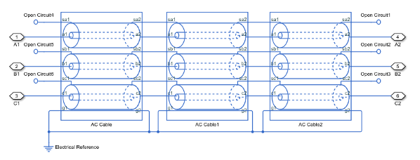
Single-point bonded continuous cables

Double-point bonded continuous cables
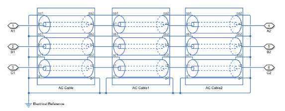
You can also model cross-bonded cables using the AC Cable (Three Phase) block.
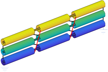
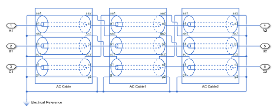
This three pi-segment cable model implements cross-bonding using expanded three-phase ports and single-phase connection lines. The sheath in the model is two-point bonded.
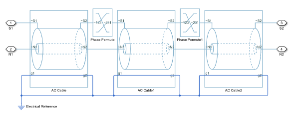
This model of blocks with composite three-phase-ports uses Phase Permute blocks to implement cross bonding. The sheath in the model is unbonded.
For an example that allows you to choose the number of segments and type of bonding, see AC Cable with Bonded Sheaths.
Three-Phase AC Cable Model
The AC Cable (Three-Phase) block uses the concept of partial inductances to calculate the inductance values. These values include the partial self-inductance of each phase, sheath, and return path and the partial mutual inductances between each:
Phase and each other phase
Phase and the sheath of that phase
Phase and the sheath of neighboring phases
Phase and the return
Sheath and each neighboring sheath
Sheath and the return
For three equivalent phases, the matrix that defines the resistance relationships for the vector [phase A; sheath A; phase B; sheath B; phase C; sheath C] is
for which R'return depends on the return parameterization method such that:
For a return parameterization based on distance and resistance
For a return parameterization based on frequency and Earth resistivity
and
where:
R is the resistance matrix.
Ra is the resistance of a particular phase.
Rs is the resistance of a particular sheath.
Rg is the resistance of the Earth- or neutral-return.
R'a is the resistance per unit length for the phase.
l is the cable length.
R's is the resistance per unit length for the sheath.
R'return is the resistance per unit length of the return. The value of R'return varies depending on the return parameterization method.
R'g is the resistance per unit length for the Earth- or neutral return.
f is the frequency that the block uses to calculate Earth-return parameters if you parameterize the block using the frequency and Earth resistivity method.
The block uses standard expressions to calculate the capacitances between:
Concentric or adjacent cylinders
Each phase and its own sheath
Each sheath and the return
The matrix that defines these capacitance relationships is
where:
C is the capacitance matrix.
Casa is the capacitance between each phase and the sheath of that phase.
Csag is the capacitance between each sheath and return.
ϵr is the permittivity of the dielectric.
ϵ0 is the permittivity of free space.
rs is the radius of the sheath.
ra is the effective radius of the conductor. For a single-strand conductor, ra is the radius of the strand.
rcable is the cable radius and rcable is greater than rs,outer.
GMR is the geometric mean radius of the conductor. For a single-strand conductor, , where rstrand is the radius of the strand.
ϵenv is the permittivity of the material between the sheathed lines and the return path.
The block uses the concept of partial inductances to calculate inductance values. These values include the partial self-inductance of each phase, sheath, and return path and the partial mutual inductances between each:
Phase and each other phase
Phase and the sheath of that phase
Phase and the sheath of neighboring phases
Phase and the return
Sheath and each neighboring sheath
Sheath and the return
The equations that define these inductance relationships are:
for which Dreturn depends on the return parameterization method such that:
For a return parameterization based on distance and resistance
For a return parameterization based on frequency and Earth resistivity
for which dab depends on the line formation parameterization method, such that:
For a trefoil line formation parameterization
For a flat line formation parameterization
where:
L is the inductance matrix.
Da is the self-inductance of a single phase through its entire path and return.
La is the partial self-inductance of each phase.
Mag is the partial mutual inductance between each phase and the Earth- or neutral-return.
Msg is the partial mutual inductance between each sheath and the Earth- or neutral-return.
The factor, is equal to , because permeability of free space, μ0, is equal to or H/m.
Ds is the self-inductance of a single sheath through its entire path and return.
Ls is the partial self-inductance of each sheath.
Masa is the partial mutual inductance between each phase and the sheath of that phase.
δ is the effective mutual inductance between a phase and the sheath of that phase.
α is the effective mutual inductance between a phase and a neighboring sheath.
Masb is the partial mutual inductance between each phase and the sheath of each neighboring phase.
Msasb is the partial mutual inductance between sheaths of different phases.
Mab is the partial mutual inductance between each phase and each other phase.
Dreturn is the effective distance to the return. The value of Dreturn varies if you use the distance/return parameterization method.
De is the effective distance to the Earth- or neutral-return.
ρ is the effective Earth resistivity for an Earth-return.
f is the frequency that is used to determine the return path properties.
dab is the effective distance between adjacent phases. The value of dab varies depending on the line parameterization method.
Dab is the center-to-center distance between adjacent phases.
A is the effective mutual inductance between phases.
S is the effective mutual inductance between sheaths.
A modal transformation that is related to the Clarke transform simplifies the equivalent circuit. The six-by-six transformation, T, is
As , applying the T transform yields the modal resistance matrix, Rm, the modal capacitance matrix, Cm, and the modal inductance matrix, Lm.
The transformed matrices are:
The transformation changes each six-by-six matrix into three uncoupled two-by-two matrices. The capacitance matrix is invariant under this transformation. The power is invariant in the transformed and untransformed domains because T is unitary.
Assumptions and Limitations
For resistance calculations, the phases are equivalent.
Relative to the phase-to-sheath capacitance and the sheath-return capacitances all other capacitances, are negligible due to the shielding provided by the conducting sheaths.
Examples
Ports
Conserving
Parameters
Extended Capabilities
Version History
Introduced in R2017b


