Map Variables for Simulink Based States
To model systems that switch between periodic or continuous time dynamics, use Simulink® based states. For more information, see Simulink Subsystems as States.
You can access inports or outports of a subsystem within a Simulink based state by using inputs and outputs in Stateflow® that have the same name as your inports and outports. For Simulink based states that are created by copying and pasting enabled subsystems and action subsystems from a library, click the Resolve undefined symbols button to map your Simulink inports and outports to Stateflow inputs and outputs automatically. See Create Inports and Outports.
If you are using a linked Simulink based state where the name of the inport or outport differs from the Stateflow chart input or output, you must ensure that your variables are mapped correctly. You can change your mappings from the Property Inspector or in the Mappings dialog box.
Map Variables in a Simulink Based State
To open the mappings dialog box, select the Simulink Based State. In the Simulink State tab, click Mappings.
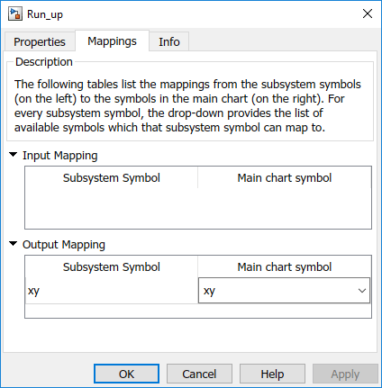
Under Input Mapping, you can specify which parent chart input maps to an inport in your Simulink subsystem.
Under Output Mapping, you can specify which parent chart output maps to an outport in your Simulink subsystem.
Note
You cannot map a local data from Stateflow chart to a data inside the Simulink Based State.