Model a Power Window Controller
This example shows how to create an interface between a Stateflow® chart that uses MATLAB® as the action language and a MATLAB app created in App Designer. For more information on connecting a Stateflow chart that uses C as the action language to a MATLAB app, see Simulate a Media Player.
In this example, an automotive power window system raises and lowers the passenger-side window in response to a pair of window control switches. The switches in the MATLAB app represent the controls on the driver and passenger doors. The app also contains several indicator lamps that monitor the status of the power window system and a button for introducing an obstacle in the path of the window.

The Stateflow chart App Interface provides a bidirectional connection between the MATLAB app and the control and plant systems in the Simulink® model. When you point a switch in the app to a new position, the chart sends a corresponding "Up," "Down," or "Neutral" command to the power window control system. Conversely, when the control system changes state, the chart enables or disables the corresponding status lamps in the app.
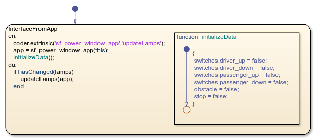
To run the example, open the Simulink model and click Run. The chart App Interface opens the app and initializes the control and plant systems in the power window system. To stop the simulation, click Stop or close the app.
Connect Chart to MATLAB App
The chart App Interface is already configured to communicate with the MATLAB app sf_power_window_app. To create a bidirectional connection between your MATLAB app and a Stateflow chart that uses MATLAB as the action language, follow these steps. In the MATLAB app:
Create a custom property to interface with the chart during simulation. The app uses this property to access chart inputs, chart outputs, and local data. For more information, see Share Data Within a Single App Designer App.
Modify the
startupFcncallback for the app by adding a new input argument and storing its value as the property that you created in the previous step. For more information, see Callbacks in App Designer.
In the Stateflow chart:
Create a local data object to interface with the app. The chart uses this local data object as an argument when it calls helper functions in the app.
Set the type of the local data object you created in the previous step to
Inherit: From definition in chart. For more information, see Specify Scope and Type of Stateflow Data.Call the
coder.extrinsicfunction to declare the app and any helper functions as extrinsic MATLAB code. For more information, see Call Extrinsic MATLAB Functions in Stateflow Charts.Run the app using the keyword
thisas an argument to give the app access to the chart during simulation. Store the value returned by the function call to the app as the local data object that you created to interface with the app.
In this example, the power window app uses a property called chart to interface with the chart App Interface. The app callbacks use this property to write to the chart outputs:
When you move the driver-side control switch to a new position, the
DriverControlValueChangedcallback sets the values ofswitches.driver_upandswitches.driver_down.When you move the passenger-side control switch to a new position, the
PassengerControlValueChangedcallback sets the values ofswitches.passenger_upandswitches.passenger_down.When you click the Obstacle button, the
ObstacleButtonPushedcallback sets the value ofobstacletotrue.When you close the app, the
UIFigureCloseRequestcallback sets the value ofstoptotrue.
Conversely, in the chart, the entry actions in the InterfaceWithApp state run the app sf_power_window_app and store the returned value as the local data object app. The chart uses this local data object when it calls the helper function updateLamps. In the app, this helper function turns the lamps on and off based on the value of the chart input lamps.

Control System Design
The power window control system uses mode logic to determine when the window should move and outputs a unified motion command to a servo motor. To lower production costs, the control system does not keep track of the window position. Instead, it relies on a signal from the servo motor to determine when the window is fully open or fully closed, or when it encounters an obstacle.
The control system meets these performance requirements:
The window must open or close completely in 5 seconds.
The motor must stop when the window reaches a fully opened or fully closed position.
The motor must be able to detect an obstacle when the window is moving up. When the motor detects an obstacle in the path of the window, the window must be lowered for one second or until the window is fully open.
The motor must stop after 10 seconds of continuous movement in any direction. This requirement provides a fail-safe protection for the window mechanism, motor, and drive.
If a control switch is pressed for less than half a second, or if it is pressed for longer than one second, the window must stop when the switch is released.
If a control switch is pressed for longer than half a second and released before one second, the window must open or close completely unless it is interrupted by a new command or by an obstacle. This requirement represents the automatic mode capability of the power window.
The driver-side control has priority over the passenger-side control.
Obstacle detection has priority over both driver-side and passenger-side controls.
The Stateflow chart Control System models an event-driven controller that satisfies these requirements. The chart consists of two states (Switch and Logic) in parallel decomposition. These states react to changes in the chart inputs, determine the operating mode of the power window system, and manage the output signals that activate the servo motor.
Monitor Controller Input
The state Switch reads the values of the chart inputs and broadcasts local events to change the operating mode of the power window system. For more information, see Broadcast Local Events to Synchronize Parallel States.
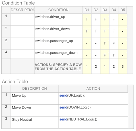
At every time step of the simulation, the state calls the truth table function checkSwitches to determine the positions of the driver-side and passenger-side control switches. Depending on the value of the input structure switches, this function broadcasts the UP, DOWN, and NEUTRAL events. Because the function ignores any input from the passenger-side control when the driver-side control is not in the "Neutral" position, the driver-side control has priority over the passenger-side control, as specified by requirement 7.
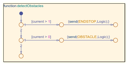
In a similar way, the state calls the graphical function detectObstacles to determine the strength of the armature current in the servo motor. If the value of current is small and nonzero, an obstacle is present so the function broadcasts the event OBSTACLE. In contrast, if the value of current is large, the window has reached a fully open or fully closed position so the function broadcasts the event ENDSTOP. Because the chart calls detectObstacles before checkSwitches, obstacle detection has priority over both driver-side and passenger-side controls, as specified by requirement 8.

Determine Operating Mode
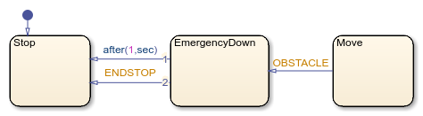
The state Logic incorporates fault detection algorithms to protect the window hardware and any obstacles in the path of the window. The state contains three substates, Stop, Move, and EmergencyDown, that represent the operating modes of the power window system.
Initially, the state Stop is active. This state contains two parallel substates named Mode and Position.
Modedetermines when the power system is ready to accept new commands from the control switches. The system is ready for new commands when both control switches are in the "Neutral" position.Positionrecords whether the window is fully open, fully closed, or somewhere in the middle. The chart makes this determination by noting the direction in which the window is moving when the servo motor reaches the end of its range.
Stop remains active until a broadcast of the events UP or DOWN indicates a command from one of the control switches. As long as the window is not fully open or fully closed, these events trigger the transition to the state Move. However, the event UP is considered invalid when the window is already fully closed. Likewise, the event DOWN is invalid when the window is fully open.
The state Move is active whenever the window is in motion. This state implements several of the power window requirements related to automatic window movement and fault detection. The state has two parallel substates named Direction and Mode.
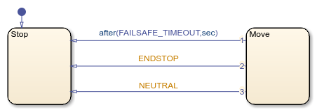
Directiondetermines the direction in which the window should move and calls the functionsgo.upandgo.down, as appropriate. These functions set the values of the output signals that control the servo motor and the "Up" and "Down" status lamps in the app.Modeimplements the automatic and manual modes of the power window specified by requirements 5 and 6. This state has three exclusive substates (Initializing,Auto, andManual). Initially, the substateInitializingis active. The substate waits for a broadcast of theNEUTRALevent, which indicates that the control switches have returned to the "Neutral" position. If the broadcast occurs within half a second ofInitializingbecoming active, the event triggers a transition to theStopstate, indicating that the window must stop moving. If the broadcast occurs after half a second but before one second ofInitializingbecoming active, the event triggers a transition to the substateAuto, indicating that the power window system is operating in its automatic mode. This substate remains active until it is interrupted by a broadcast of the eventsENDSTOP(when the window is fully open or fully closed),OBSTACLE(when the window encounters an obstacle), orUPorDOWN(when the system receives a new command from one of the control switches). Finally, if the broadcast does not occur before one second ofInitializingbecoming active, the temporal logic expressionafter(1,sec)triggers the transition to the substateManual. This substate remains active until a broadcast of the eventNEUTRALtriggers the transition back to theStopstate.
Independent of whether the system is in automatic or manual mode, the chart transitions directly from Move to Stop on the broadcast of the event ENDSTOP or when Move is active for longer than FAILSAFE_TIMEOUT seconds, as specified by requirements 2 and 4. By default, the value of this constant is set to 10.

Detect Obstacles
When the window encounters an obstacle, the applied force on the window increases the load on the servo motor and causes a rise in the armature current. By monitoring for sharp increases in the armature current, the system detects obstacles in the path of the window.
In this example, a Simulink subsystem simulates the servo motor. The position of the window is computed by an Integrator (Simulink) block with saturation limits of 0 (fully open) and 10 (fully closed). Because the input to this block has a gain of 2, the window opens and closes completely in 5 seconds, as specified by requirement 1. When the Integrator block reaches a saturation point, the system output armature current increases to 10. This value indicates that the window is fully open or fully closed.

To introduce an obstacle in the path of the window, click the Obstacle button in the app while the window is moving up. The App Interface chart responds by sending a positive signal to the servo motor, which in turn produces a small rise in the armature current. In the Control System chart, the function detectObstacles registers this change in current and broadcasts the event OBSTACLE. In the Logic state, this event triggers the transition from the substate Move to the substate EmergencyDown. While this substate is active, the system moves the window down for one second or until the window is fully open. Then, the chart transitions back to the substate Stop, indicating that the window must stop moving, as specified by requirement 3.
See Also
after | hasChanged | send | this | coder.extrinsic (MATLAB Coder) | Integrator (Simulink)