Develop Gesture Based Motor-Control Robot Using Arduino and Simulink
This example shows how to use Simulink® Support Package for Arduino® Hardware and an Arduino hardware board to develop gesture based motor-control robot.
Introduction
Simulink Support Package for Arduino Hardware enables you to build a simple gesture based motor-control robot by interfacing APDS9960 sensor and motor drives with Arduino hardware board. A gesture based motor-control robot controls the robot movement by analyzing hand gestures information received from the APDS9960 sensor.
This example uses a two-wheeled robot built with Arduino hardware board, where the robot controls the motor direction based on the gestures detected from the algorithm and the APDS9960 sensor.
Prerequisites
Complete the Get Started with Arduino Hardware and Communicating with Arduino Hardware examples.
Required Hardware
To run this example, you will need the following hardware.
Arduino hardware board
DC Motor
APDS9960 sensor
Batteries
Chassis with wheels to set up the above hardware and make a robot
Hardware Setup
Sensor Setup
1. Build a two-wheeled robot with a APDS9960 sensor mounted on it.
2. Connect APDS9960 sensor to the Arduino hardware board through standard I2C connections. For more information on I2C Communication, refer to Support I2C Communication
DC Motor Setup
1. Use two motors to control the direction of the robot and connect them through PCA9685 or the L293D chip based motor shields. Power the driver hardware with external power supply such as batteries and link the two motors to the two wheels of the chassis. You can refer to the motors as left and right depending on their connections to the robot.
2. Connect the enable pin, input A and input B of the motor shield to GPIO pins of the Arduino hardware board. The enable pin must be connected to one of the supported PWM pins. For more information on pin mapping, refer to Pin Mapping for Arduino Timer Dependent Blocks.
Simulink Model
Open the arduino_robotics_gesturebasedcontrol Simulink model.

The model is divided into three areas based on the functionality in each area.
Data Source
The readily available APDS9960 sensor block from Simulink Support Package for Arduino Hardware is used in this subsystem to represent the connection of APDS9960 sensor to the Arduino Hardware board. This block outputs the gesture data detected in upward, downward, left and right directions. For more information on configuring different parameters of the parameters of the block, refer to APDS9960 Sensor.
Gesture Detection
This subsystem receives gesture data detected in upward, downward, left and right directions from the data source and processes the data to detect gesture. The subsystem outputs this detected gesture, which controls the motor direction and power.
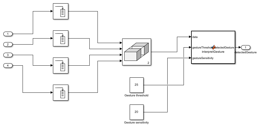
The algorithm in the 'interpretGesture' MATLAB Function block interprets gestures based on gesture data from the UDLR gesture sensor, gesture threshold and gesture sensitivity.
Motor Control
This block receives detected gesture, which decides the speed and direction of motors.
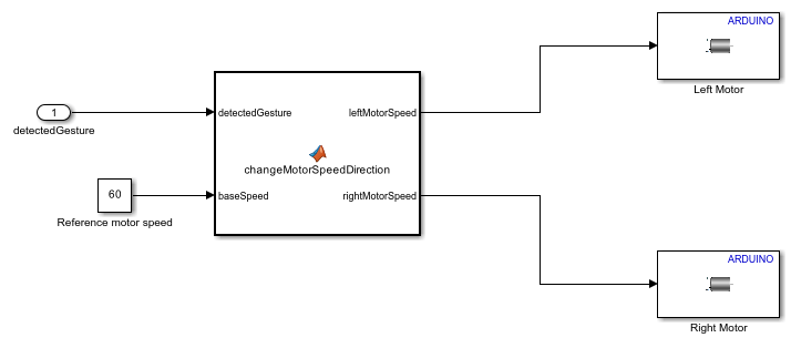
The algorithm in the MATLAB Function block changes motor speed and direction.
Deploy Simulink Model on Arduino Hardware
Follow these steps to deploy the Simulink model.
1. Open the arduino_robotics_gesturebasedcontrol Simulink model.
2. On the Modeling tab of the model, click Model Settings. In the Configuration Parameters dialog box, click Hardware Implementation on the left pane and set the Hardware board parameter to Arduino.
3. On the Hardware tab of the Simulink model, in the Mode section, select Run on board.
4. In the Deploy section of the Simulink model, click Build, Deploy & Start. The generated code is built on the Arduino hardware and runs automatically.
5. Observe the developed robot moving in different directions with varying speed from detected gestures through the live APDS9960 sensor feed.
See Also
You can also select a web site from the following list:
Americas
- América Latina (Español)
- Canada (English)
- United States (English)
Europe
- Belgium (English)
- Denmark (English)
- Deutschland (Deutsch)
- España (Español)
- Finland (English)
- France (Français)
- Ireland (English)
- Italia (Italiano)
- Luxembourg (English)
- Netherlands (English)
- Norway (English)
- Österreich (Deutsch)
- Portugal (English)
- Sweden (English)
- Switzerland
- United Kingdom (English)