Publish Data from Arduino Blocks and Read Data on Web Browser Using WebSocket Protocols
This example shows how to use the Simulink® Support Package for Arduino® Hardware to publish and subscribe data from various Arduino blocks to a WebSocket server and to read data on a web browser in a WebSocket client.
Supported Arduino Boards
Arduino MKR 1000
Arduino MKR WIFI 1010
Arduino Nano 33 IoT
Introduction
This example shows how you can adopt WebSocket communication protocols for Arduino boards. This protocol enables the interaction between a web browser (or any other client application) and a web server, facilitating instantaneous data transfer to and from the WebSocket server. The JavaScript code running in the browser establishes a WebSocket connection between the web page and the Arduino board. Various user interfaces are used on the web page to communicate with the Simulink model deployed on the Arduino board. Most browsers support WebSocket protocol, including Google Chrome®, Microsoft Edge®, Internet Explorer®, Firefox®, Safari®, and Opera®.
The counter, frequency, and duty cycle values from the Input Capture block and duty cycle of the PWM signal from the Digital Input block are published from the Arduino board to a WebSocket server. Whereas, you can change the LED ON/OFF position and the PWM values on the client application running on the web browser. The client application sends these values to the server application running on the Arduino board.
Prerequisite
We recommend that you complete the Get Started with Arduino Hardware example.
Required Hardware
This example uses the Arduino MKR 1000 board. You can use any of the Arduino boards from the list of supported boards.
Micro USB cable
Task 1: Hardware Connection Setup
Connect the host computer to the Arduino board using a micro USB cable. The Arduino board and the host computer must be connected on the same wireless network for successful communication.
Connect pin 3 of PWM 1 to pin 10 of the Input Capture block.
Connect pin 8 of PWM 2 to pin 7 of the Digital Input block.
Task 2: Configure Simulink Model
This support package provides a preconfigured model to publish the data on the WebSocket server.
Open the arduino_websocket_tutorial Simulink model.
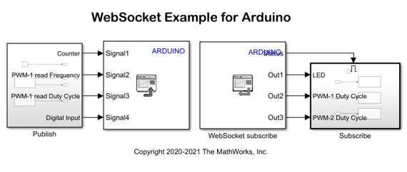
The model can be divided into two sections: WebSocket Publish and WebSocket Subscribe.
A. WebSocket Publish
This section publishes data from the Arduino board to a WebSocket server identified by an IP address and a port. The published data is in the JSON format, which can be interpreted by a WebSocket client to visualize the data.
1. Publish Subsystem: Consists of a limited counter, Input Capture block, and Digital Input block.
You can configure the following parameters in the Publish subsystem:
a. Counter Limited
Set the Upper Limit of the counter to
20.Set the Sample time to
0.1seconds.
b. Input Capture
Set the Input capture pin number to
10.Set the Sample time to
0.1seconds.
c. Digital Input Block
Set the Pin number to
7.The Pin mode is set to
Default.Set the Sample time to
0.1seconds.
2. WebSocket Publish: Publishes input data from the counter and the Input Capture and Digital Input blocks over the WebSocket client.
You can configure the following parameters in the WebSocket Publish block:
a. Set the Server port to 9000. You can configure this parameter according to the server port of your Arduino board. Ensure to configure the same port number for the WebSocket Publish and WebSocket Subscribe blocks.
b. Set the Number of Inputs to 4, so that they correspond to the inputs from the Publish subsystem and the frequency input from the Input Capture block.
B. WebSocket Subscribe
This section subscribes to the data received by a WebSocket server identified by an IP address and a port. The received data must be in JSON format, which can be interpreted by a WebSocket client to manipulate the data.
1. Subscribe Subsystem: Consists of an LED and two PWM blocks with output frequencies of 1Hz and 1000Hz.
You can configure the following parameters in the Subscribe subsystem:
a. Digital Write
Set the Pin number to
6to connect to the onboard LED of the Arduino board.
b. PWM - 1
Set the Pin number to
3.Specifythe Frequency and set the Desired frequency to |1000|Hz.
c. PWM -2
Set the Pin number to
8.Specifythe Frequency and set the Desired frequency to |1|Hz.
2. WebSocket Subscribe: Subscribes to the data received from the LED and PWM blocks.
You can configure the following parameters in the WebSocket subscribe block:
a. Set the Port to 9000. You can configure this parameter according to the server port of your Arduino board. Ensure to configure the same port number for the WebSocket Publish and WebSocket Subscribe blocks.
b. Set the source to obtain properties of JSON data in the Specify Output Info via parameter. This example uses the default value.
c. Set the Number of Outputs to 3, so that they correspond to the inputs to the LED and two PWM blocks.
d. Specify the Data Size and Data Type as 1 and uint8, respectively, for all three outputs.
e. Set the Sample time to 0.5 seconds.
Task 3: Run Simulink Model
To select your Arduino board, in the Hardware tab, click Hardware Settings. In the Configuration Parameters dialog box, in the Hardware Implementation pane, select from the list of supported Arduino boards in the Hardware boards parameter. Click Apply.
To set the wireless network properties, select Configuration Parameters > Hardware Implementation > Target hardware resources > WiFi properties. Enter the details and click Apply.
On the Hardware tab of the Simulink model, in the Mode section, select Run on board and then click Build, Deploy & Start.
The Simulink model is deployed on the Arduino board. Once the WebSocket client is connected, the Arduino board starts sending data from the counter and the Input Capture and Digital Input blocks to the WebSocket server in the JSON format.
Task 4: Access Data from WebSocket Client
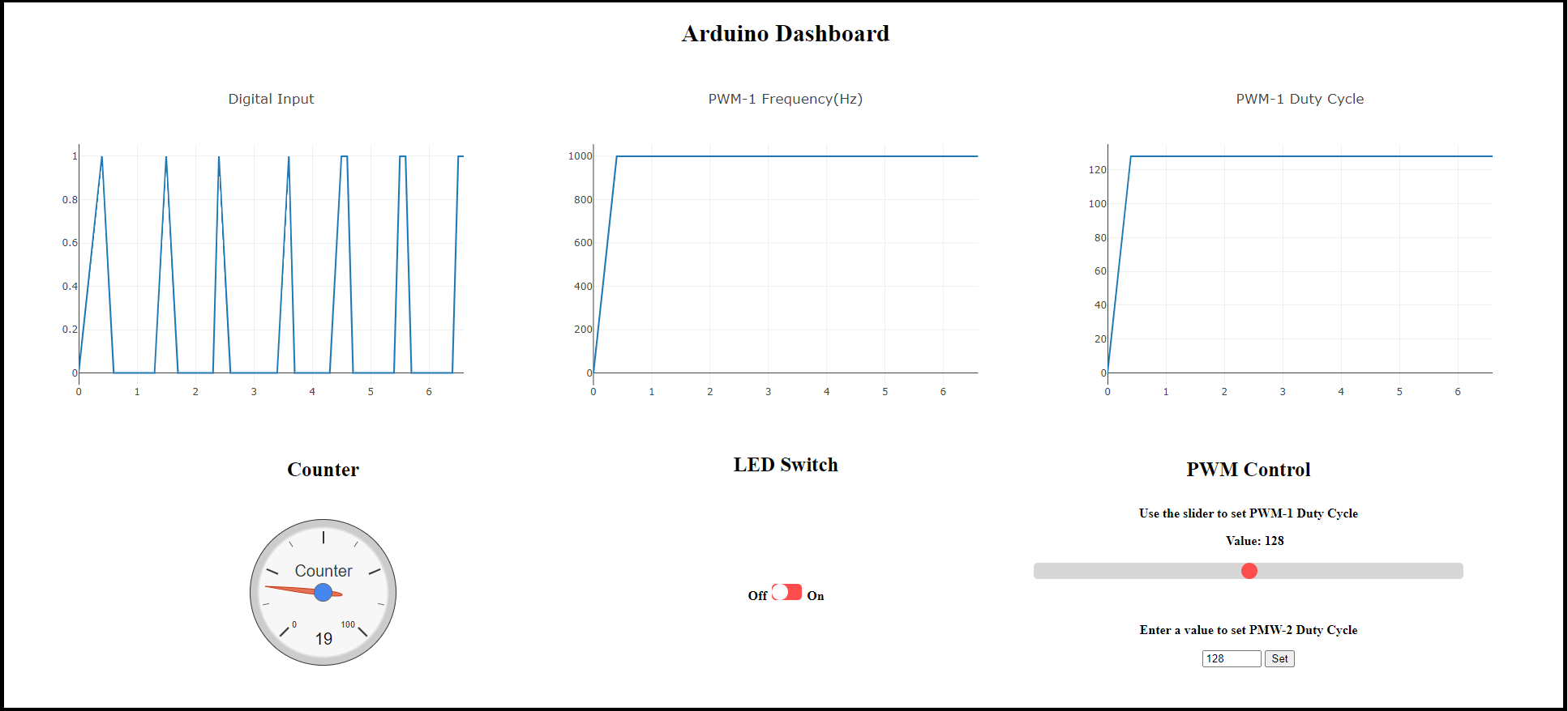
This example provides a JavaScript-based web browser dashboard, Arduino Dashboard, that can read the data available in JSON format in a WebSocket server.
To access this dashboard and open it in your default web browser, run the following command at the MATLAB Command Window:
web('Arduino_WebSocket_DashControl.html', '-browser')Tip: The web browser dashboard is best viewed in a Google Chrome or Firefox browser.
Configure Arduino IP Address in Web Browser
Copy the file path of the Arduino Dashboard web page.
Navigate to the file path that contains the Arduino_WebSocket_Dashcontrol.html page.
Open the HTML page in any editor.
After deploying the Simulink model on the Arduino board, the Diagnostics Viewer dialog box opens. Optionally, you can go to the Debug tab and click Diagnostics.
Copy the IP address mentioned in the Diagnostics Viewer dialog box.
Paste the Arduino IP address and port number in the var host and var port fields, respectively, of the HTML page.
The dashboard is preconfigured using JavaScript to send JSON data to the server application running on the Arduino board identified using the IP address 192.168.0.100 and the port 9000.
While the model runs on the Arduino board, you can perform and observe these changes on the Arduino Dashboard page.
Toggle the LED Switch and observe pin 6 on the Arduino board. The LED turns ON and OFF according to the position of the switch on the dashboard.
Use the slider to change the duty cycle of PWM - 1 connected to the Input Capture block. Observe the changes in the graph of the PWM - 1 Duty Cycle parameter.
Observe the 1000Hz frequency set for the Input Capture block in the graph of the PWM - 1 Frequency parameter.
Use the up and down arrows to change the duty cycle of the PWM - 2 parameter connected to the Digital Input block. Click Set to apply the changes. Observe the changes in the graph of Digital Input port.
The Counter increments from 0 to 19 and then resets to 0.
Note: The PWM - 1 Duty Cycle parameter set on pin 8 may not be read accurately by the Digital Input block using the slider.
Other Things to Try
Customize the Arduino Dashboard page on the WebSocket client for different Arduino blocks and user interfaces.
You can also select a web site from the following list:
Americas
- América Latina (Español)
- Canada (English)
- United States (English)
Europe
- Belgium (English)
- Denmark (English)
- Deutschland (Deutsch)
- España (Español)
- Finland (English)
- France (Français)
- Ireland (English)
- Italia (Italiano)
- Luxembourg (English)
- Netherlands (English)
- Norway (English)
- Österreich (Deutsch)
- Portugal (English)
- Sweden (English)
- Switzerland
- United Kingdom (English)