Processor-in-the-Loop Verification of Simulink Models
This example shows how to use Embedded Coder® Support Package for ARM® Cortex®-A Processors to verify code using PIL simulation.
Introduction
Configure a Simulink® model to run as a processor-in-the-loop (PIL) simulation. In a PIL simulation, the generated code runs on an emulated ARM Cortex-A9 (QEMU) emulator. The results of the PIL simulation are transferred to Simulink® to verify the numerical equivalence of the simulation and code generation results. The PIL verification process is a crucial part of the design cycle to check that the behavior of the generated code matches the design. For more information PIL simulation techniques, see SIL and PIL Simulations. For more information on the QEMU emulator, see the QEMU website.
Requirements
PIL Verification Using PIL Block
This section show how to automatically generate a PIL block for the Controller subsystem to verify the behavior of the generated code.
1. Open the arm_cortex_a_pil_block model. The model is a test harness system for a plant-controller system.

2. On the Hardware tab of the Simulink Toolstrip, click Hardware Settings. In the Configuration Parameters dialog box, set Code Generation > Verification > Advanced parameters > Create block to PIL. Click OK.
3. Right-click the Controller Subsystem block and select Block Parameters (Subsystem). In the Function Block Parameters dialog box, select Treat as atomic unit. Click OK.
4. Right-click the Subsystem block and select C/C++ Code > Deploy this Subsystem to Hardware.
5. In the Build code for Subsystem dialog box, click Build. A new model, untitled*, contains a PIL block named after the subsystem.

6. Copy the PIL block from untitled* to the test harness model. Close the untitled* model without saving.
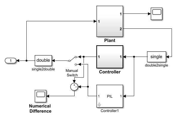
7. On the Simulation tab of the Simulink Toolstrip, click Run to start the simulation with the generated PIL block executing on the ARM Cortex-A (QEMU).
In a PIL simulation, the test harness model executes in Simulink while the PIL block executes on the embedded processor. The simulation runs for the duration specified by the Simulation stop time value. During the simulation, you can:
Use the Manual Switch to toggle between the two outputs
Observe the scope for numerical differences.
Perform PIL Verification Using Model Block PIL
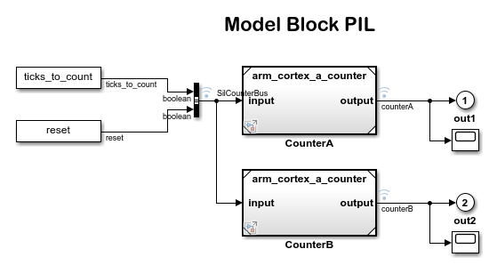
This section shows how to create and test a subsystem block using Model block PIL workflow.
1. Open the arm_cortex_a_model_pil_block model. The CounterA model block contains the simulation model. CounterB model block contains the model to test in a PIL simulation. For more information on model referencing, see Reference Existing Models.
2. On the Apps tab of the Simulink Toolstrip, under Code Verification, Validation and Test, click SIL/PIL Manager.
3. On the SIL/PIL tab of the Simulink Toolstrip, set System Under Test to Model blocks in SIL/PIL mode.
4. Configure and run CounterA block in PIL simulation mode. Open the CounterA block mask by right-clicking on the block and select Block Parameters (ModelReference). In the Function Block Parameters: CounterA dialog box, set Simulation mode to Processor-in-the-loop (PIL). Click OK.
5. On the SIL/PIL tab of the Simulink Toolstrip, click Run Verification to start the PIL simulation with the refernce model block executing on the ARM Cortex-A (QEMU).
6. When the model runs, Scope1 displays the PIL simulation output running on the ARM Cortex-A (QEMU). Scope2 shows the normal mode simulation output.
Verification Using PIL Simulation for Top Models
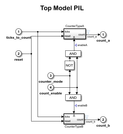
This section shows how to create and test a top-model PIL simulation.
1. Open the arm_cortex_a_top_model_pil model.
2. On the Apps tab of the Simulink Toolstrip, under Code Verification, Validation, and Test, click SIL/PIL Manager.
3. On the SIL/PIL tab of the Simulink Toolstrip, set System Under Test to Top Model and set SIL/PIL Mode to Processor-in-the-Loop (PIL).
4. To start the PIL simulation of the model, on the SIL/PIL tab, click Run Verification.
When the PIL simulation stops, the Simulation Data Inspector automatically opens to show a comparison of the outputs, count_a and count_b, between the simulation and the PIL execution.

Related Links
You can also select a web site from the following list:
Americas
- América Latina (Español)
- Canada (English)
- United States (English)
Europe
- Belgium (English)
- Denmark (English)
- Deutschland (Deutsch)
- España (Español)
- Finland (English)
- France (Français)
- Ireland (English)
- Italia (Italiano)
- Luxembourg (English)
- Netherlands (English)
- Norway (English)
- Österreich (Deutsch)
- Portugal (English)
- Sweden (English)
- Switzerland
- United Kingdom (English)