Signal Monitoring and Parameter Tuning of Generated PWM Output
This example shows how to use PWM Output block in a Simulink® model to generate PWM signals using Embedded Coder® Support Package for STMicroelectronics® STM32 Processors.
Introduction
In this example you will learn how to use and generate code for PWM Output block in Simulink® model for STMicroelectronics® NUCLEO-F429ZI board to generate PWM signals on Channel 1 and Channel 2 of Timer module 1. You will also learn how to monitor and tune the frequency and duty cycle of the generated PWM output
Prerequisites
Complete the following tutorials:
Required Hardware
To run this example you need the following hardware:
STMicroelectronics NUCLEO-F429ZI board.
Micro USB cable.
Jumper wires for connections.
Model

Using this model you can generate PWM signals on channel 1, channel 1 complementary and channel 2 output pins of timer 1 module.
Configure PWM Output Block to Generate PWM Signals on Channels 1 and 2 of Timer Module 1
In this task,
PWM output block is configured to generate PWM outputs for TIM1 timer module. The channels 1 and 2 are enabled and duty cycle in percentage for the enabled channels are given as input. The frequency of the timer in counts is also given as input using
Freq countport. The timer counter can be enabled/disabled using the CEN input port.The PWM output pins are connected to the GPIO pins configured in external interrupt mode with rising/falling edge detection. The hardware interrupt block is configured to read these GPIO pins when their corresponding external events are triggered. This will help in monitoring the generated PWM signals in the Data Inspector
1. Open the stm32_pwmgettingstarted target model.
2. Configure the blocks. Double-click the block to open the block parameter dialog box.
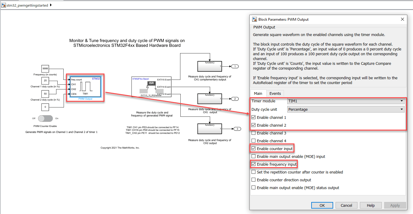
In PWM Output block,
TIM1is selected as the Timer module. The Channels 1 and 2 are enabled and Duty cycle unit inPercentageis given as input to the corresponding channel inputs.The Enable frequency input is selected to give the timer frequency in counts as input. The Enable counter input is selected and the slider switch is used to enable/disable the counter.
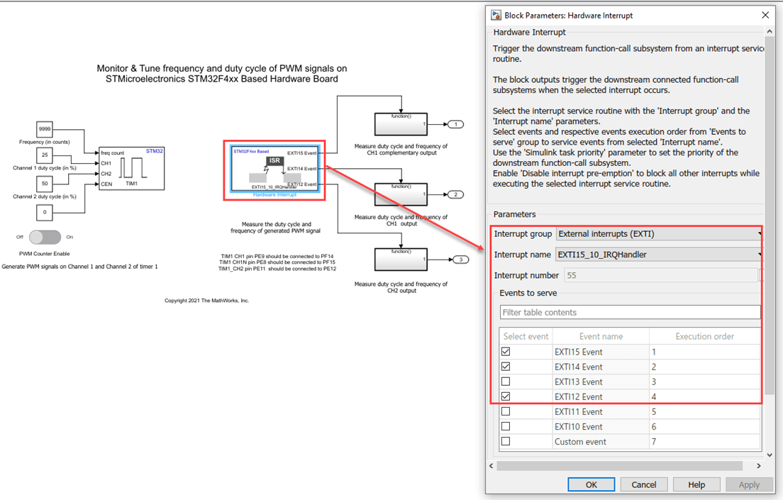
The Hardware Interrupt block is configured for
EXTI15_10_IRQHandlerandEXTI15,EXTI14andEXTI12events are selected.The pins
PF14(connected to CH1 output),PF15(connected to CH1 complementary output) andPE12(connected to CH2 output) are read inside the function call subsystems connected toEXTI15,EXTI14andEXTI12events.
3. Create a new STM32CubeMX project or browse to an existing STM32CubeMX project. Launch the STM32CubeMX project in the STM32CubeMX tool. For details, see Getting Started with STMicroelectronics STM32 Processor Based Boards.
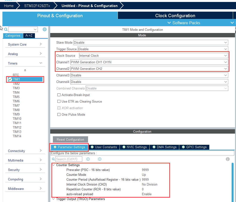
4. Perform the following configurations in STM32CubeMX project to enable and configure the TIM1 channels:
Select the Clock Source as
Internal.Select
PWM Generation CH1 and CH1Nfor Channel 1 andPWM Generation CH2for Channel 2.Set the Prescaler as
9999Set the Counter Period (AutoReload Register - 16 bits value) with the initial frequency in counts.
Select Counter Mode as
Up.
5. Perform the following configuration to enable and configure the GPIO pins in external interrupt mode.
In the Pinout view, search for pins
PF14,PF15,PE12and right click on pins and configure them asGPIO_EXT14,GPIO_EXT115, andGPIO_EXTI12respectively.In System core > GPIO, ensure these pins are configured for GPIO mode as
External interrupt mode for rising/falling edge detection.

Note: The hardware board has USART pins connected to ST-LINK. To run the model in External mode without the need for an external FTDI, ensure to configure the GPIO settings for USART. For more information on USART pins connected to the ST-LINK, refer to the respective board's schematic diagram.

6. In your STM32CubeMX project, ensure to perform the following configurations:
Enable Do not generate the main() under Project Manager > Project.
Disable Generate under root under Project Manager > Project.
Under Project Manager > Advanced Settings > Driver Selector, select low level (LL) drivers for the peripherals.
Under Project Manager > Advanced Settings > Generate Functions Calls, disable Do Not Generate Function Calls for all the peripheral initialization function calls.
Under Project Manager > Advanced Settings > Generate Function Calls, disable Visibility (Static) for all the peripheral initialization function calls.
Save the project.
Monitor and Tune the Model
When you perform Monitor & Tune action for the model, the host computer communicates with the target, on which the generated executable runs.
1. Open the Hardware tab and click Monitor & Tune. You can observe from the Diagnostic Viewer that the code is generated for the model and the host connects to the target after loading the generated executable.

2. While the model is running, observe the GPIO output signals using the Data Inspector to monitor the duty cycle and frequency of the generated PWM signals.
Change the frequency and duty cycle using the PWM Output block input ports in runtime and observe the changes in the corresponding PWM outputs in Data Inspector.
The PWM signals will start when counter is turned on and stopped when counter is turned off.
Analysis of PWM Output
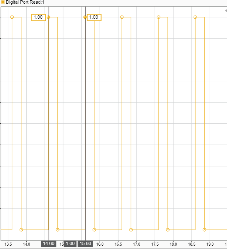
The PWM Output analysis is based on Timer 1 Channel 1 output on pin PF_14. From the above figure Time period of the generated PWM is 1s.
The PWM time period is calculated as follows:
PWM frequency = Clock Frequency/((1+ Frequency input in counts)(1 + Preload register value))
PWM time period = 1/(PWM frequency)
Where,
Frequency in counts = 9999
Preload register value = 9999
Clock frequency = 100MHz
So, PWM frequency = (100 x 10^6)/(10000 * 10000) = 1 Hz PWM time period = 1s
All the above configurations are preconfigured for this example.
Other Things to try:
Use other counter modes:
DownandCenteraligned modes by configuring in STM32CubeMX project.Configure Hardware Interrupt block to trigger function call subsystems for Timer events like update event, capture compare events etc. You can also generate these events using input ports by enabling the inputs for corresponding events under Events section in the block.
In center aligned mode, set the repetition counter in STM32CubeMX project as odd value. Observe that update events are generated on underflow. Now enable the Set repetition counter after counter is enabled in the PWM Output block and observe the update events are generated on overflow.
See Also
You can also select a web site from the following list:
Americas
- América Latina (Español)
- Canada (English)
- United States (English)
Europe
- Belgium (English)
- Denmark (English)
- Deutschland (Deutsch)
- España (Español)
- Finland (English)
- France (Français)
- Ireland (English)
- Italia (Italiano)
- Luxembourg (English)
- Netherlands (English)
- Norway (English)
- Österreich (Deutsch)
- Portugal (English)
- Sweden (English)
- Switzerland
- United Kingdom (English)