imkeepborder
Description
J = imkeepborder(I)I that are lighter
than their surroundings and connected to the image border, while suppressing all
other structures. If I is a binary image, then a structure is a connected group of white pixels. Use
this function to keep the image border while clearing structures that are not
touching the border. The output image J is grayscale or binary,
depending on the input.
J = imkeepborder(I,Name=Value)imkeepborder(I,Borders=["left" "right"])
retains only the structures touching the left or right image border.
Examples
Keep Objects Connected to Image Border
Read a binary image (a postprocessed image of microscopic quartz columnar grains [2]) into the workspace, and display it.
originalBW = imread("quartz_columns.png");
imshow(originalBW)
Keep only the light objects in the image that are connected to the image border, removing the rest.
BWborder=imkeepborder(originalBW);
imshow(BWborder)

Keep Objects Connected to Select Image Borders
Read a binary image (a postprocessed image of microscopic quartz columnar grains [2]) into the workspace, and display it.
originalBW = imread("quartz_columns.png");
imshow(originalBW)
Keep only the objects which are connected to the top or bottom border of the image, and remove the rest.
BWkeep2B = imkeepborder(originalBW,Borders=["top" "bottom"]);
imshow(BWkeep2B)

Input Arguments
I — Grayscale or binary image
numeric array | logical array
Grayscale or binary image, specified as a numeric or logical array.
Data Types: single | double | int8 | int16 | int32 | uint8 | uint16 | uint32 | logical
Name-Value Arguments
Specify optional pairs of arguments as
Name1=Value1,...,NameN=ValueN, where Name is
the argument name and Value is the corresponding value.
Name-value arguments must appear after other arguments, but the order of the
pairs does not matter.
Example: imkeepborder(I,Borders=["left" "right"]) retains light
structures touching the left or right image border of an image.
Borders — Image borders at which to retain structures
vector of strings | N-by-2 matrix of 0s and
1s
Image borders at which to retain structures, specified as a vector of
strings or an N-by-2 matrix of 0s
and 1s:
Vector of strings — Specifies at which borders of a 2-D image to retain structures as any combination of
"left","right","top", and"bottom". When you specifyIas a 2-D image, the default value ofBordersis["left" "right" "top" "bottom"].N-by-2 matrix of
0s and1s — Specifies borders of an N-dimensional image at which to retain structures, where the first element of each row represents the first border in the corresponding dimension and the second element represents the second border in that dimension. For example, ifBorders(k,1)is1, then structures which touch the first border in the k-th dimension are selected. IfBorders(k,2)is1, then structures which touch the second border in the k-th dimension are selected. For example, specifyingBorders = [0 0; 1 1; 0 0]is equivalent to specifyingBorders = ["left" "right"]. The default value ofBordersfor N-dimensional images isones(ndims(I),2), which specifies to retain structures touching all borders of the image.
Connectivity — Pixel connectivity
4 | 8 | 6 | 18 | 26 | 3-by-3-by- ... -by-3 matrix of 0s and
1s
Pixel connectivity, specified as one of the values in this table or a
3-by-3-by- ... -by-3 matrix of 0s and
1s. The default connectivity is
8 for 2-D images and 26 for
3-D images.
Value | Meaning | |
|---|---|---|
Two-Dimensional Connectivities | ||
| Pixels are connected if their edges touch. The neighborhood of a pixel are the adjacent pixels in the horizontal or vertical direction. |
Current pixel is shown in gray. |
| Pixels are connected if their edges or corners touch. The neighborhood of a pixel are the adjacent pixels in the horizontal, vertical, or diagonal direction. |
Current pixel is shown in gray. |
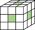
Three-Dimensional Connectivities | ||
| Pixels are connected if their faces touch. The neighborhood of a pixel are the adjacent pixels in:
|
Current pixel is shown in gray. |
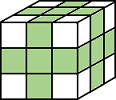
| Pixels are connected if their faces or edges touch. The neighborhood of a pixel are the adjacent pixels in:
|
Current pixel is center of cube. |
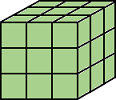
| Pixels are connected if their faces, edges, or corners touch. The neighborhood of a pixel are the adjacent pixels in:
|
Current pixel is center of cube. |


For higher dimensions, imkeepborder uses the
default value conndef(ndims(I),'maximal')
Data Types: double | logical
Output Arguments
Algorithms
imkeepborder uses morphological reconstruction where:
The mask image is the input image.
The marker image is 0 everywhere except along the border, where it equals the mask image.
References
[1] Soille, Pierre. Morphological Image Analysis: Principles and Applications Berlin ; New York: Springer, 1999, 164–165.
[2] Molnar, Ian. Uniform quartz - Silver nanoparticle injection experiment, Digital Rocks Portal (April 2016). Accessed March 10, 2023. https://www.digitalrocksportal.org/projects/44, made available under the ODC-BY 1.0 Attribution License.
Extended Capabilities
Version History
Introduced in R2023b
See Also
You can also select a web site from the following list:
Americas
- América Latina (Español)
- Canada (English)
- United States (English)
Europe
- Belgium (English)
- Denmark (English)
- Deutschland (Deutsch)
- España (Español)
- Finland (English)
- France (Français)
- Ireland (English)
- Italia (Italiano)
- Luxembourg (English)
- Netherlands (English)
- Norway (English)
- Österreich (Deutsch)
- Portugal (English)
- Sweden (English)
- Switzerland
- United Kingdom (English)