NR Positioning Reference Signal
This example shows how to configure the time-frequency aspects of the new radio (NR) positioning reference signal (PRS). The example shows how different PRS resource set configurations affect the time-frequency structure of the PRS using 5G Toolbox™ features.
Introduction
According to TR 22.872 [1], these 5G use cases require finding the accurate and real-time location of nodes in the wireless network:
Location-based services, such as accurate positioning for shared bikes and location-based advertising
Industry-related use cases, such as waste management and collection
eHealth-related use cases, such as medical equipment location in hospitals and patient location outside of hospitals
Emergency-related and mission-critical-related use cases
Road-related use cases, such as road-user charging
Rail- and maritime-related use cases, such as asset and freight tracking
Aerial-related use cases, such as unmanned aerial vehicle missions and operations
To find the position of a node, downlink reference signals are used at the user equipment (UE) side. The existing downlink reference signals, like the channel state information reference signal and the synchronization signals, are not used for the position estimation due to these limitations:
These reference signals are not capable of detecting a sufficient number of neighbor access network nodes (gNBs) because of the interference from the adjacent cells when the signals from multiple cells collide in both the time-domain and frequency-domain. Due to this interference, signals from nearby cells shadow the weak signals from far away cells, causing difficulty for the UE to detect far away cells or gNBs. This difficulty results in a loss in hearability.
These reference signals also have weak correlation properties due to low resource element (RE) density and their RE pattern might not spread across all of the subcarriers in the frequency-domain.
To overcome these limitations, the 3GPP introduced a new reference signal called the PRS in Release 16 of 5G specification, with a high RE density and with the correlation properties better than that of existing reference signals due to the diagonal or staggered PRS RE pattern. Hearability of the PRS is achieved with a concept called muting. With PRS muting, multiple cells transmit the PRS in a coordinated manner by muting the relevant PRS transmission occasions to avoid the interference from adjacent cells. This example demonstrates the time-frequency aspects of the PRS and shows how to configure PRS muting.
As per the 3GPP standard, you can configure a UE with one or more downlink PRS positioning frequency layer configurations. A PRS positioning frequency layer is defined as a collection of PRS resource sets with each PRS resource set defining a collection of PRS resources. All of the PRS resource sets defined in the PRS positioning frequency layer are configured with these common parameters:
Subcarrier Spacing: Subcarrier spacing for all PRS resource sets in a PRS positioning frequency layer, specified as 15, 30, 60, or 120. Use the
SubcarrierSpacingproperty of thenrCarrierConfigto set the subcarrier spacing of a PRS resource set.Cyclic Prefix: Cyclic prefix for all PRS resource sets in a PRS positioning frequency layer, specified as
'normal'or'extended'. Use theCyclicPrefixproperty of thenrCarrierConfigobject to set the cyclic prefix of a PRS resource set.PRS Point A: Absolute frequency of reference resource block or common resource block. The lowest subcarrier of this reference resource block is known as PRS Point A. The 5G specification defines the PRS frequency resource allocation relative to PRS point A. The example shows how to configure the start of PRS frequency-domain allocation using 5G Toolbox™ features and its relation with the standard notion.
The 5G Toolbox™ offers the PRS symbols and indices generation with a configuration object nrPRSConfig and functions nrPRS and nrPRSIndices. The nrPRSConfig object bundles all of the parameters related to a PRS resource set.
PRS Slot Configuration
These properties of the nrPRSConfig object control the PRS slot configuration.
PRSResourceSetPeriod: Slot periodicity and offset (0-based) of a PRS resource setPRSResourceOffset: Slot offset (0-based) of each PRS resource defined relative to the slot offset of the PRS resource setPRSResourceRepetition: Repetition factor of all PRS resources in a PRS resource setPRSResourceTimeGap: Slot offset between two consecutive repetition indices of all PRS resources in a PRS resource set
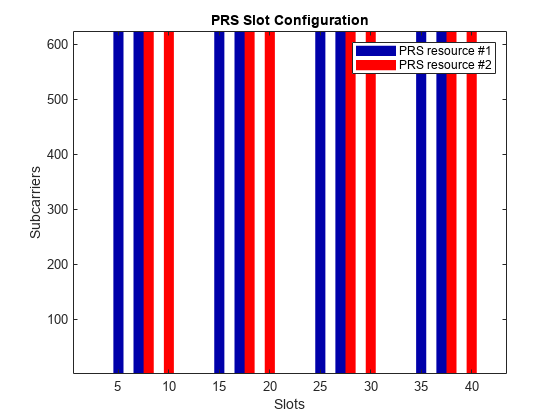
The Figure 1 illustrates the case of a PRS resource set with 2 PRS resources. The PRS resource set period is 10 slots and the PRS resource set offset is 3 slots (0-based). The first PRS resource offset is 1 slot (0-based) and the second PRS resource offset is 4 slots (0-based). The PRS resource repetition factor is 2 (which means each PRS resource is repeated twice in all PRS resource set instances), and the PRS resource time gap is 2 (which means an offset of 2 slots).

Configure the PRS slot configuration parameters and plot the carrier grid in a slot level to highlight the slots in which PRS resources are present.
% Set carrier parameters
carrier = nrCarrierConfig;
carrier.SubcarrierSpacing = 15;
carrier.CyclicPrefix = 'Normal';

% Set parameters related to PRS slot configuration
prs = nrPRSConfig;
prs.PRSResourceSetPeriod = [10 3];
prs.PRSResourceOffset = [1 4];
prs.PRSResourceRepetition = 2;
prs.PRSResourceTimeGap = 2;
numSlots = 43;                                       % Consider 43 slots to compare the plot with Figure 1
plotTitle = 'PRS Slot Configuration';
plotGrid(carrier,prs,numSlots,'SlotFill',plotTitle); % Slot numbers on the x-axis of the MATLAB plot are 1-based
PRS Muting Configuration
You can mute a PRS resource in two ways:
Mute the PRS resource set instances using the properties
MutingPattern1andMutingBitRepetitionof thenrPRSConfigobjectMute the PRS resource repetition indices using the property
MutingPattern2of thenrPRSConfigobject
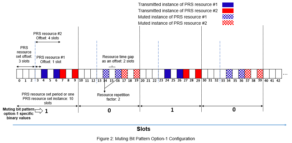
MutingPattern1: A binary vector that controls the muting of PRS resource set instances. Each element in the binary vector controls the muting of all PRS resources in a PRS resource set instance (one instance corresponds to one period of the PRS resource set). The first element in the binary vector corresponds to the first PRS resource set instance, the second element corresponds to the second PRS resource set instance, and so on.
A binary value of 1 indicates that all PRS resources in a PRS resource set instance are transmitted.
A binary value of 0 indicates that all PRS resources in a PRS resource set instance are muted.
The Figure 2 illustrates the case of muting bit pattern option-1 as [1 0] in addition to the previous PRS slot configuration which is shown in Figure 1. In this case, the effective muting bit pattern option-1 at PRS resource set instance level is [1 0 1 0 1 0 ...], which is the repeated pattern of MutingPattern1.
Solid fill in the figure represents the PRS resource set instances that are transmitted, and pattern fill in the figure represents the PRS resource set instances that are muted or not transmitted.
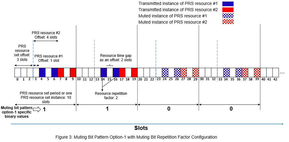
MutingBitRepetition: Number of consecutive PRS resource set instances (say N) corresponding to a single element of the MutingPattern1 binary vector. The first element in the MutingPattern1 binary vector corresponds to N consecutive instances of a PRS resource set, the second element corresponds to the next N consecutive instances of a PRS resource set, and so on.
The Figure 3 illustrates the case of muting pattern option-1 as [1 0] and muting bit repetition factor as 2 in addition to the previous PRS slot configuration which is shown in Figure 1. With these parameters, the effective muting bit pattern at PRS resource set instance level is [1 1 0 0 1 1 0 0 ...].
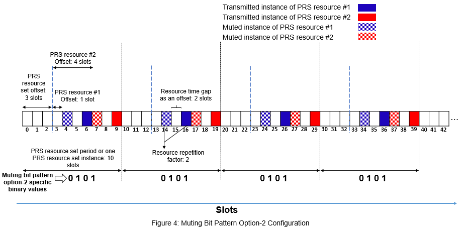
MutingPattern2: A binary vector that controls the muting of PRS resource repetition indices in all active PRS resource set instances. The first element in the binary vector corresponds to the first repetition index of a PRS resource, the second element corresponds to the second repetition index of a PRS resource, and so on. The length of the binary vector is equal to the value of the PRSResourceRepetition property and the same binary vector is applicable to all PRS resources in a PRS resource set.
The Figure 4 illustrates the case of muting bit pattern option-2 as [0 1] in addition to the previous PRS slot configuration which is shown in Figure 1. In this case, the effective muting bit pattern option-2 at PRS resource repetition index level is [0 1 0 1 0 1 ...], which is the repeated pattern of MutingPattern2.
When you configure both the MutingPattern1 and MutingPattern2 properties, the effective muting bit pattern is equal to the bit-wise AND of muting bit pattern option-1 and muting bit pattern option-2.
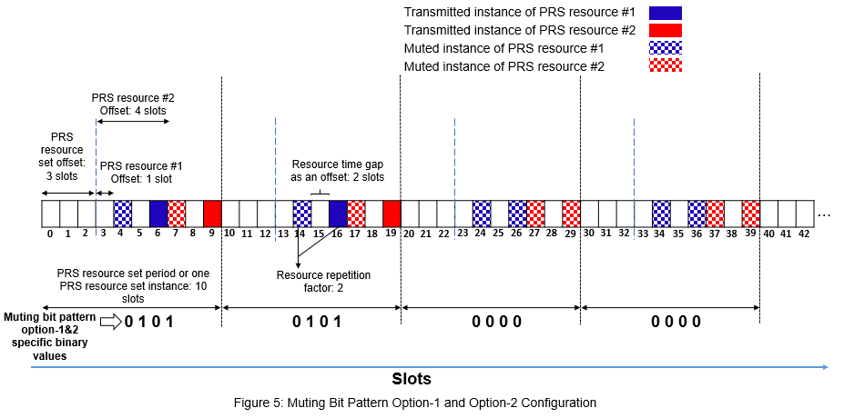
The Figure 5 illustrates the case of muting bit pattern option-1 as [1 0], muting bit repetition factor as 2, and muting bit pattern option-2 as [0 1] in addition to the previous PRS slot configuration which is shown in Figure 1. With these parameters, the effective muting bit pattern option-1 at PRS resource set instance level is [1 1 0 0 1 1 ...] and the effective muting bit pattern option-2 at PRS resource repetition index level is [0 1 0 1 0 1 ...].
For the specified configuration, as the number of PRS resources is 2 and the PRS resource repetition factor is 2, one PRS resource set instance contains four resource instances. And below are the muting bit pattern option-1 and the muting bit pattern option-2 at PRS resource repetition index level:
Muting bit pattern option-1 at PRS resource repetition index level, binaryVec1 = [1 1 1 1 1 1 1 1 0 0 0 0 0 0 0 0 1 1 1 1 1 1 1 1 ...].
Muting bit pattern option-2 at PRS resource repetition index level, binaryVec2 = [0 1 0 1 0 1 0 1 0 1 0 1 0 1 0 1 0 1 0 1 0 1 0 1 ...].
Effective muting bit pattern at PRS resource repetition index level is the bit-wise AND of binaryVec1 and binaryVec2, which is equal to [0 1 0 1 0 1 0 1 0 0 0 0 0 0 0 0 0 1 0 1 0 1 0 1 ...]. You can observe this pattern in the Figure 5.
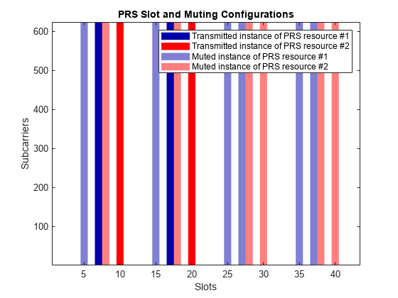
Configure the PRS muting patterns in addition to the previous PRS slot configuration in prs. MATLAB code generates the PRS resources as empty for the slots that are muted. This example highlights the muted slots with light shade in the generated plots for the easy comparison with the Figures 2 to 5.
prs.MutingPattern1 = [1 0];                          % Use [] to disable the muting bit pattern option-1
prs.MutingBitRepetition = 2;
prs.MutingPattern2 = [0 1];                          % Use [] to disable the muting bit pattern option-2
plotTitle = 'PRS Slot and Muting Configurations';
plotGrid(carrier,prs,numSlots,'SlotFill',plotTitle); % Slot numbers on the x-axis of the MATLAB plot are 1-based
PRS Time-Domain and Frequency-Domain Allocation
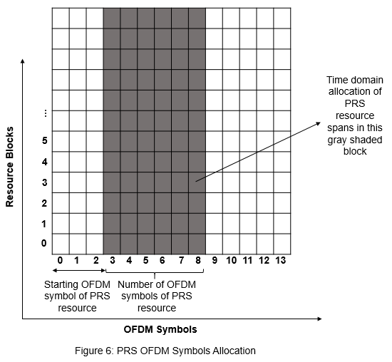
These properties of the nrPRSConfig object control the time-domain allocation of a PRS resource.
NumPRSSymbols(): Number of consecutive OFDM symbols in a slot that are allocated for each PRS resource in a PRS resource set.SymbolStart(): Starting OFDM symbol (0-based) of each PRS resource in a PRS resource set. This property is defined relative to the first OFDM symbol of the slot (symbol #0).
The OFDM symbols allocated for a PRS resource are defined as .
The Figure 6 illustrates the case, where the number of OFDM symbols allocated for a PRS resource is 6 and the starting OFDM symbol of PRS resource allocation is 3 (0-based).
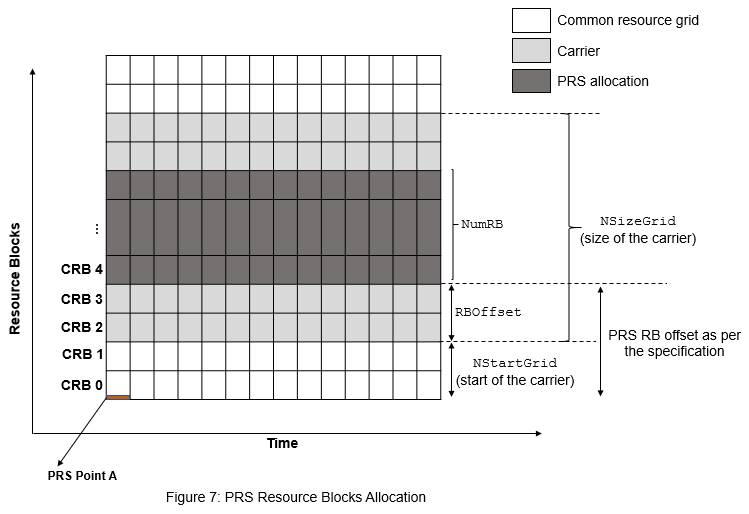
These properties of the nrPRSConfig object control the frequency-domain allocation of a PRS resource at RB level granularity.
NumRB: Number of physical resource blocks (PRBs) allocated for all PRS resources in a PRS resource set.RBOffset: Starting PRB index (0-based) of all PRS resources in a PRS resource set. This property is defined relative to the carrier resource grid, but the specification defines this offset relative to common resource block 0 (CRB 0) (the Figure 7 highlights these notations).
The Figure 7 illustrates the frequency-domain allocation of a PRS resource and the carrier.
These properties of the nrPRSConfig object control the frequency-domain allocation of a PRS resource at RE level granularity.
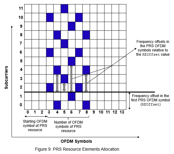
CombSize(): RE density of all PRS resources in a PRS resource set. For example, if you configure the value as , every th RE in the PRB is allocated for the PRS.REOffset(): Starting RE offset (0-based) in the first OFDM symbol of each PRS resource in a PRS resource set. The relative RE offsets of the next or the following PRS OFDM symbols are defined relative to thisREOffsetvalue, as shown in the table in the Figure 8.
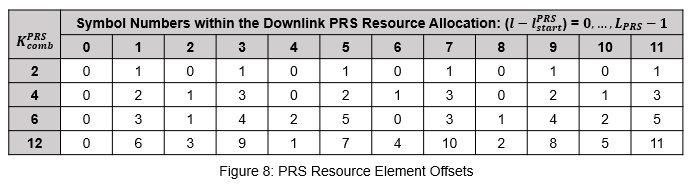
Consider the number of OFDM symbols allocated for a PRS resource as 6, the starting OFDM symbol of PRS resource allocation as 3 (0-based), the PRS comb size as 4, and the RE offset in the first OFDM symbol as 2 (0-based). For PRS comb size 4, the relative RE offsets of the following PRS OFDM symbols are calculated based on row 2 from the table in the Figure 8.
For the specified configuration, the OFDM symbol numbers within the PRS resource allocation are (0-based).
From the table in the Figure 8, the relative RE offsets () in the PRS OFDM symbols are [0 2 1 3 0 2]. The arrows in the Figure 9 highlight these relative offsets. The figure shows a single PRB in one slot to highlight the RE level pattern.
Effective RE offsets (the second term of the calculation, as defined in TS 38.211 Section 7.4.1.7.3 [2]) in the PRS OFDM symbols are (0-based).
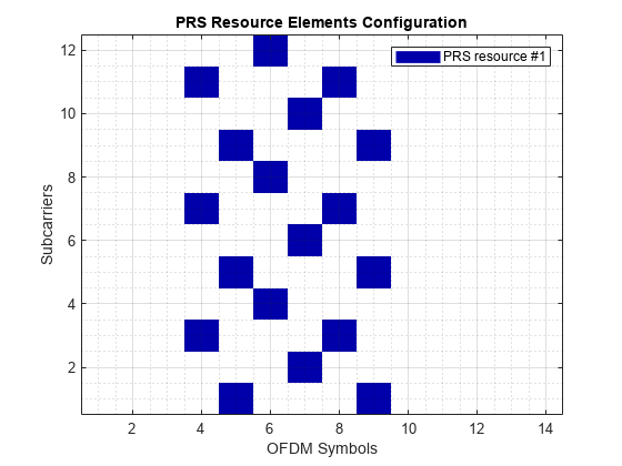
Configure the RE and symbol level allocation of the PRS. To observe the frequency-domain pattern at the RE level, this code uses a single PRB in one slot.
carrier.NSizeGrid = 1;
prs = nrPRSConfig;
prs.NumPRSSymbols = 6;
prs.SymbolStart = 3;
prs.NumRB = 1;
prs.RBOffset = 0;
prs.CombSize = 4;
prs.REOffset = 2;
numSlots = 1;                                      % Consider one slot to highlight the RE pattern in the MATLAB plot
plotTitle = 'PRS Resource Elements Configuration';
plotGrid(carrier,prs,numSlots,'REFill',plotTitle); % OFDM symbol and subcarrier numbers in the MATLAB plot are 1-based
grid on;
grid minor;
PRS Sequence Identity
The NPRSID property of the nrPRSConfig object is used in the initialization of a pseudo-random binary sequence to generate the PRS symbols, as defined in TS 38.211 Section 7.4.1.7.2 [2].
Summary and Further Exploration
The example shows how to configure the time-frequency aspects of the PRS and how different PRS resource set configurations affect the time-frequency structure of the PRS.
Configure multiple PRS resources with different time and frequency allocation aspects and slot configuration aspects, and then observe the variations in the slot allocation and RE positions. Try different muting configurations (different combinations of muting bit pattern option-1 and option-2), and then see the variations in the grid.
References
3GPP TR 22.872. "Study on positioning use cases." 3rd Generation Partnership Project; Technical Specification Group Services And System Aspects.
3GPP TS 38.211. "NR; Physical channels and modulation (Release 16)." 3rd Generation Partnership Project; Technical Specification Group Radio Access Network.
Local functions
This example uses these local functions to plot the time-frequency aspects of all PRS resources configured in a PRS resource set.
function plotGrid(carrier,prs,numSlots,flag,imTitle)
%   plotGrid(CARRIER,PRS,NUMSLOTS,FLAG,IMTITLE) plots the carrier grid by
%   considering these inputs:
%
%   CARRIER  - Carrier specific configuration object
%   PRS      - Positioning reference signal configuration object
%   NUMSLOTS - Number of slots over which the function plots the
%              carrier grid
%   FLAG     - Flag to consider the plot style, specified as
%              'SlotFill' or 'REFill'. The 'SlotFill' option highlights the
%              slots in which the PRS is present. The 'REFill' option
%              highlights the REs in which the PRS is present.
%   IMTITLE  - Title for the plot

    [transmittedSlots,mutedSlots] = getTransmittedAndMutedSlots(carrier,prs,numSlots); % Of size numSlots-by-numRes
    numRes = size(transmittedSlots,2);
    rng(37);                  % Set RNG state for repeatability
    tempColors = reshape(rand((numRes-2)*3,1),[],3);
    map = [1 1 1;...          % White color
           0 0 0.6667;...     % Blue color
           1 0 0;...          % Red color
           tempColors];
    resScalings = 1:numRes+1; % 1 for white color, 2 for blue color, and 3 for red color, and so on
    prsREGrid = zeros(carrier.NSizeGrid*12,carrier.SymbolsPerSlot*numSlots);
    prsSlotGrid = resScalings(1)*ones(carrier.NSizeGrid*12,numSlots);                  % For white background

    figure();
    % Plot PRS slot grid
    image(abs(prsSlotGrid));

    % Apply colormap to image
    colormap(map);

    for slotIdx = 0:numSlots-1
        if strcmpi(flag,'REFill')
            carrier.NSlot = slotIdx;
            ind = nrPRSIndices(carrier,prs,'OutputResourceFormat','cell');
            sym = nrPRS(carrier,prs,'OutputResourceFormat','cell');
            slotGrid = nrResourceGrid(carrier);
            for resIdx = 1:numel(ind)
                slotGrid(ind{resIdx}) = resScalings(resIdx+1)*abs(sym{resIdx});
            end
            prsREGrid(:,(1:carrier.SymbolsPerSlot)+carrier.SymbolsPerSlot*slotIdx) = slotGrid;

            % Replace all zero values of carrier grid with proper scaling
            % for white background
            prsREGrid(prsREGrid == 0) = resScalings(1);

            % Plot carrier grid
            image(abs(prsREGrid));
            axis xy;

            % Apply colormap to image
            colormap(map);

            % Add labels to x-axis and y-axis
            xlabel('OFDM Symbols');
            ylabel('Subcarriers');

            % Generate lines
            L = line(ones(numRes),ones(numRes),'LineWidth',8);
            % Index color map and associate selected colors with lines
            set(L,{'color'},mat2cell(map(resScalings(2:end),:),ones(1,numRes),3));
            % Create legend
            legendNames = cell(1,numRes);
            for resIdx = 1:numRes
                legendNames{resIdx} = ['PRS resource #' num2str(resIdx)];
            end
            legend(legendNames{:});
        else % 'SlotFill'
            axis xy;
            hold on;
            for resIdx = 1:numRes
                ismuted = mutedSlots(slotIdx+1,resIdx);
                isTransmitted = transmittedSlots(slotIdx+1,resIdx);
                temp = [slotIdx+1 slotIdx+1];
                color = map(resIdx+1,:);
                if isTransmitted
                    hT(resIdx) = patch([temp(1)-0.5 temp(1)-0.5 temp(end)+0.5 temp(end)+0.5],[1 624 624 1],...
                        color,'LineStyle','none'); %#ok<AGROW>
                end
                if ismuted
                    hM(resIdx) = patch([temp(1)-0.5 temp(1)-0.5 temp(end)+0.5 temp(end)+0.5],[1 624 624 1],...
                        color,'LineStyle','none','FaceAlpha',0.5); %#ok<AGROW>
                end
            end
        end
    end

    % Add title to image
    title(imTitle);
    if strcmpi(flag,'SlotFill')
        % Add labels to x-axis and y-axis
        xlabel('Slots');
        ylabel('Subcarriers');

        % Create legend
        legendNames = cell(1,numRes);
        legendNamesTxRes = cell(1,numRes);
        legendNamesMutedRes = cell(1,numRes);
        for resIdx = 1:numRes
            legendNames{resIdx} = ['PRS resource #' num2str(resIdx)];
            legendNamesTxRes{resIdx} = ['Transmitted instance of PRS resource #' num2str(resIdx)];
            legendNamesMutedRes{resIdx} = ['Muted instance of PRS resource #' num2str(resIdx)];
        end
        if sum(mutedSlots(:)) > 0
            legend([hT hM],[legendNamesTxRes legendNamesMutedRes]);
        else
            legend(hT,legendNames);
        end
    end
end

function [transmittedSlots,mutedSlots] = getTransmittedAndMutedSlots(carrier,prs,numSlots)
%   [TRANSMITTEDSLOTS,MUTEDSLOTS] = getTransmittedAndMutedSlots(CARRIER,PRS,NUMSLOTS)
%   returns logical arrays to give information about transmitted slots
%   TRANSMITTEDSLOTS and muted slots MUTEDSLOTS for all PRS resources by
%   considering these inputs:
%
%   CARRIER  - Carrier specific configuration object
%   PRS      - Positioning reference signal configuration object
%   NUMSLOTS - Number of slots for which the output is returned

    % Take copy of input PRS configuration to retain input muting
    % configuration unchanged for further processing
    prs1 = prs;

    % Extract PRS configuration without considering muting aspects
    prs1.MutingPattern1 = [];
    prs1.MutingBitRepetition = 2;
    prs1.MutingPattern2 = [];
    numResOffVal = numel(prs1.PRSResourceOffset);
    numSymStartVal = numel(prs1.SymbolStart);
    numPRSSymVal = numel(prs1.NumPRSSymbols);
    numREOffVal = numel(prs1.REOffset);
    numNPRSIDVal = numel(prs1.NPRSID);

    % Calculate the number of PRS resources configured in a PRS
    % resource set
    numRes = max([numResOffVal, numSymStartVal, numPRSSymVal, ...
        numREOffVal, numNPRSIDVal]);
    PRSPresenceWithOutMuting = zeros(numSlots,numRes);
    for slotIdx = 0:numSlots-1
        carrier.NSlot = slotIdx;
        [~,PRSPresence] = nr5g.internal.validateAndSchedulePRS(carrier,prs1);
        PRSPresenceWithOutMuting(slotIdx+1,:) = PRSPresence;
    end

    % Consider PRS configuration with muting aspects
    prs1.MutingPattern1 = prs.MutingPattern1;
    prs1.MutingBitRepetition = prs.MutingBitRepetition;
    prs1.MutingPattern2 = prs.MutingPattern2;
    PRSPresenceWithMuting = zeros(numSlots,numRes);
    for slotIdx = 0:numSlots-1
        carrier.NSlot = slotIdx;
        [~,PRSPresence] = nr5g.internal.validateAndSchedulePRS(carrier,prs1);
        PRSPresenceWithMuting(slotIdx+1,:) = PRSPresence;
    end

    % Identify transmitted and muted slots based on PRS scheduling
    transmittedSlots = PRSPresenceWithMuting;                                 % Of size numSlots-by-numRes
    mutedSlots = PRSPresenceWithOutMuting ~= PRSPresenceWithMuting;           % Of size numSlots-by-numRes
end