5G NR NTN Preset Waveform Generation
R2026bThis example shows how to generate standard-compliant 5G New Radio (NR) non-terrestrial network (NTN) preset waveforms for frequency range 1 (FR1) and frequency range 2 (FR2). You can specify the preset name, channel bandwidth, subcarrier spacing (SCS), orbit type, and duplex mode.
The example supports these preset categories.
NR-SAN test models - Defines NTN satellite access node (SAN) test models for evaluating radio frequency (RF) transmitter conformance, including error vector magnitude (EVM), adjacent channel leakage ratio (ACLR), and emissions.
R.PDSCH RMCs - Defines NTN user equipment (UE) receiver reference measurement channels (RMCs) for evaluating physical downlink shared channel (PDSCH) demodulation performance.
R.PDCCH RMCs - Defines NTN UE receiver RMCs for evaluating physical downlink control channel (PDCCH) demodulation performance.
Downlink FRCs for receiver requirements - Defines NTN UE receiver fixed reference channels (FRCs) for evaluating receiver sensitivity and selectivity requirements.
Uplink RMCs - Defines NTN UE transmitter RMCs for evaluating transmitter conformance, including EVM, maximum power reduction (MPR), and ACLR performance.
Uplink FRCs - Defines SAN receiver FRCs for evaluating receiver conformance, including sensitivity and dynamic range performance.
Introduction
The 3GPP 5G NR standard defines waveform configurations for NTN conformance testing in these specifications.
TS 38.181 defines NR-SAN test models for satellite base station RF transmitter testing.
TS 38.108 defines uplink FRCs for SAN receiver testing.
TS 38.101-5 defines R.PDSCH, R.PDCCH, downlink FRCs for receiver requirements, and uplink RMCs for NTN UE conformance.
NTN waveforms incorporate several satellite-specific adaptations, including:
Discontinuous slot scheduling - Supports non-geostationary satellite orbit (NGSO) configurations, including low Earth orbit (LEO) and medium Earth orbit (MEO) satellites, as well as geostationary satellite orbit (GSO) systems, through orbit-dependent inactive-slot patterns. These patterns accommodate satellite link-budget constraints and hybrid automatic repeat request (HARQ) timing requirements.
Half-duplex frequency division duplex (HD-FDD) mode - Allocates guard-time symbols to accommodate UE transmit-to-receive and receive-to-transmit switching.
pi/2-binary phase shift keying (pi/2-BPSK) modulation - Provides a low peak-to-average power ratio (PAPR) uplink waveform for power-constrained satellite UEs.
The hNRNTNPresetConfig object contains a Carrier property that stores an nrDLCarrierConfig or nrULCarrierConfig object. You can pass this carrier configuration object directly to the nrWaveformGenerator function and modify it after creation to define custom test scenarios.
For information on generating preset waveforms for 5G terrestrial (non-satellite) scenarios, see the 5G NR-TM and FRC Waveform Generation example.
NR-SAN Test Model Waveform Generation
TS 38.181 Section 4.9.2 defines NR-SAN test models for RF transmitter conformance testing of SAN. The test models have varying PDSCH characteristics depending on the test purpose, including full-band or single physical resource block (PRB) allocations, support for one or multiple modulation schemes, and power boosting or deboosting configurations. Common characteristics of these test models include PDSCH mapping type A, DM-RS type 1 configured with two positions per slot in FR1 and one position per slot in FR2, and a PDCCH configuration with a single allocated control channel candidate. The waveforms do not use transport coding and use either all-zero or PN23 input data. All test models operate in FDD mode and generate a 10 ms waveform corresponding to one radio frame.
NTN SAN RF transmitter conformance tests use these test models.
TM1.1, TM3.1, and TM3.2 support error vector magnitude (EVM) measurements defined in Section 6.5.2.
All test models support frequency error measurements defined in Section 6.5.1.
TM1.1 supports time alignment error (Section 6.5.3), ACLR (Section 6.6.3), operating-band unwanted emissions (Section 6.6.4), transmitter spurious emissions (Section 6.6.5), and transmitter intermodulation (Section 6.6.6) measurements.
Supported NR-SAN Test Model Presets
You can view the list of available FR1 and FR2 NR-SAN test model presets by using the FR1NRSANTestModels and FR2NRSANTestModels properties of the hNRNTNPresetConfig object.
FR1 test models:
NR-SAN-FR1-TM1.1 defines a full-band quadrature phase shift keying (QPSK) waveform for EVM, ACLR, emissions, and frequency error testing.
NR-SAN-FR1-TM1.2 defines a single-PRB QPSK waveform for EVM testing.
NR-SAN-FR1-TM2 defines a full-band QPSK waveform with boosted and deboosted PRBs for EVM and frequency error testing.
NR-SAN-FR1-TM3.1 defines a full-band 64-symbol quadrature amplitude modulation (64QAM) waveform for EVM testing.
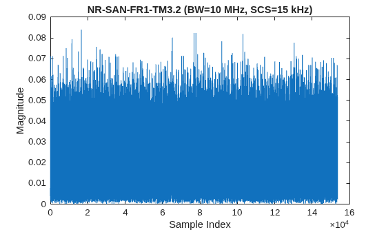
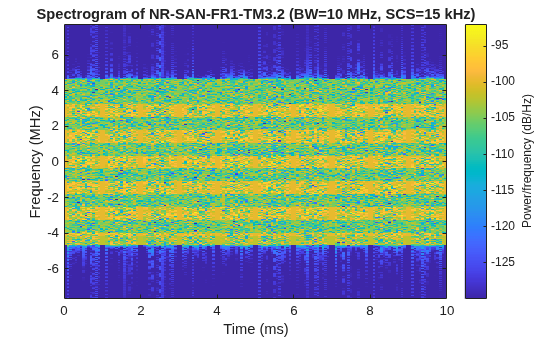
NR-SAN-FR1-TM3.2 defines a partial-band waveform that combines 16-symbol quadrature amplitude modulation (16QAM) and QPSK modulation schemes for EVM testing.
NR-SAN-FR1-TM3.3 defines a full-band QPSK waveform with the PDSCH disabled for power control and time alignment error testing.
FR2 test models:
NR-SAN-FR2-TM1.1 defines a full-band QPSK waveform for EVM, ACLR, and emissions testing.
NR-SAN-FR2-TM2 defines a full-band QPSK waveform with boosted and deboosted PRBs for EVM testing.
NR-SAN-FR2-TM3.1 defines a full-band 64QAM waveform for EVM testing.
fr1NRSANTestModels = hNRNTNPresetConfig.FR1NRSANTestModels
fr1NRSANTestModels = 6×1 string
    "NR-SAN-FR1-TM1.1"
    "NR-SAN-FR1-TM1.2"
    "NR-SAN-FR1-TM2"
    "NR-SAN-FR1-TM3.1"
    "NR-SAN-FR1-TM3.2"
    "NR-SAN-FR1-TM3.3"
fr2NRSANTestModels = hNRNTNPresetConfig.FR2NRSANTestModels
fr2NRSANTestModels = 3×1 string
    "NR-SAN-FR2-TM1.1"
    "NR-SAN-FR2-TM2"
    "NR-SAN-FR2-TM3.1"
Set NR-SAN Test Model
Configure an NR-SAN test model preset by specifying the preset name using the hNRNTNPresetConfig object.
Optional name-value arguments include:
ChannelBandwidth- Channel bandwidth in MHz. When you specify this argument as[], the object uses 10 MHz for FR1 and 100 MHz for FR2.SubcarrierSpacing- Subcarrier spacing in kHz. When you specify this argument as[], the object uses 15 kHz for FR1 and 120 kHz for FR2.NCellID- Physical layer cell identity. The default value is 1.
presetName ="NR-SAN-FR1-TM3.2"; channelBandwidth = []; % Channel bandwidth in MHz, [] represents 10 MHz for FR1 and 100 MHz for FR2 subcarrierSpacing = []; % Subcarrier spacing in kHz, [] represents 15 kHz for FR1 and 120 kHz for FR2 % Create preset configuration ntnTM = hNRNTNPresetConfig(presetName, ... ChannelBandwidth=channelBandwidth, ... SubcarrierSpacing=subcarrierSpacing); % View the configured carrier ntnTM.Carrier
ans =
  nrDLCarrierConfig with properties:

                Label: 'NR-SAN-FR1-TM3.2'
       FrequencyRange: 'FR1'
     ChannelBandwidth: 10
              NCellID: 1
         NumSubframes: 10
     InitialNSubframe: 0
     WindowingPercent: 0
           SampleRate: []
     CarrierFrequency: 0
          SCSCarriers: {[1×1 nrSCSCarrierConfig]}
       BandwidthParts: {[1×1 nrWavegenBWPConfig]}
              SSBurst: [1×1 nrWavegenSSBurstConfig]
              CORESET: {[1×1 nrCORESETConfig]}
         SearchSpaces: {[1×1 nrSearchSpaceConfig]}
                PDCCH: {[1×1 nrWavegenPDCCHConfig]}
                PDSCH: {[1×1 nrWavegenPDSCHConfig]  [1×1 nrWavegenPDSCHConfig]  [1×1 nrWavegenPDSCHConfig]}
                CSIRS: {[1×1 nrWavegenCSIRSConfig]}

   Constant properties:
    FR1BandwidthTable: [3×16 table]
    FR2BandwidthTable: [4×7 table]
Generate NR-SAN Test Model Waveform
Generate the baseband waveform using the nrWaveformGenerator function.
[tmWaveform,tmWaveInfo] = nrWaveformGenerator(ntnTM.Carrier);
Visualize NR-SAN Test Model Waveform
Plot the time-domain magnitude and spectrogram of the generated test model waveform.
% Plot waveform magnitude
figure
plot(abs(tmWaveform))
title(presetName + " (BW=" + ntnTM.Carrier.ChannelBandwidth + " MHz, SCS=" + ntnTM.Carrier.SCSCarriers{1}.SubcarrierSpacing + " kHz)")
xlabel("Sample Index")
ylabel("Magnitude")
% Plot spectrogram
sampleRate = tmWaveInfo.ResourceGrids.Info.SampleRate;
nfft = tmWaveInfo.ResourceGrids.Info.Nfft;
figure
spectrogram(tmWaveform(:,1),ones(nfft,1),0,nfft,"centered",sampleRate,"yaxis",MinThreshold=-130)
title("Spectrogram of " + presetName + " (BW=" + ntnTM.Carrier.ChannelBandwidth + " MHz, SCS=" + ntnTM.Carrier.SCSCarriers{1}.SubcarrierSpacing + " kHz)")
R.PDSCH Reference Measurement Channel Waveform Generation
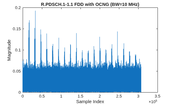
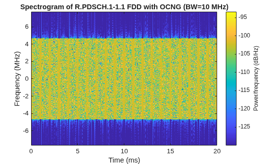
TS 38.101-5 Annex A.3.2 defines R.PDSCH RMCs for NTN UE receiver PDSCH demodulation performance testing. The tests verify that the UE can successfully decode a reference PDSCH and achieve the required throughput under NTN fading tapped delay line (TDL) channel conditions specified by the NTN-TDL-A and NTN-TDL-D channel models with satellite Doppler. R.PDSCH waveforms include transport-block-coded PDSCH transmissions that use redundancy version 0, front-loaded mapping type A with additional DM-RS positions, and a control resource set (CORESET) with PDCCH transmissions in the first symbols of each slot. Slot 0 does not carry the reference PDSCH because it is reserved for the synchronization signal block (SSB). All resource elements use uniform power levels, and the transport block data source uses the ITU PN9 sequence.
NTN UE receiver tests use these R.PDSCH RMCs for:
PDSCH demodulation throughput testing defined in TS 38.101-5 Section 7, which verifies that the UE achieves at least 70% throughput at the specified SNR.
Radio link monitoring testing defined in Section 7.6, which verifies out-of-sync and in-sync detection performance.
Channel state information (CSI) reporting testing defined in Section 7.9, which evaluates channel quality indicator (CQI) and rank indicator (RI) reporting accuracy under NTN channel conditions.
Supported R.PDSCH RMC Presets
You can view the list of available R.PDSCH presets using the RPDSCH property of the hNRNTNPresetConfig object.
FR1 15 kHz presets:
R.PDSCH.1-1.1 defines a single-layer QPSK waveform with a code rate of 308/1024 and 52 physical resource blocks (PRBs) for PDSCH demodulation performance testing.
R.PDSCH.1-1.2 defines a single-layer 16QAM waveform with a code rate of 490/1024 and 25 PRBs for PDSCH demodulation performance testing.
R.PDSCH.1-1.3 defines a single-layer 64QAM waveform with a code rate of 466/1024 and 270 PRBs for PDSCH demodulation performance testing.
R.PDSCH.1-2.1 defines a two-layer QPSK waveform with a code rate of 308/1024 and 52 PRBs for rank-2 PDSCH demodulation performance testing.
R.PDSCH.1-2.2 defines a two-layer QPSK waveform with a code rate of 308/1024 and 40 PRBs for radio link monitoring.
R.PDSCH.1-2.3 defines a two-layer 16QAM waveform with a code rate of 490/1024 and 25 PRBs for CSI reporting.
FR2 120 kHz presets:
R.PDSCH.3-3.1 defines a single-layer QPSK waveform with a code rate of 308/1024 and 132 PRBs for PDSCH demodulation performance testing.
R.PDSCH.3-4.1 defines a two-layer QPSK waveform with a code rate of 308/1024 and 132 PRBs for rank-2 PDSCH demodulation performance testing.
FR1 30 kHz preset:
R.PDSCH.4-1.1 defines a single-layer QPSK waveform with a code rate of 308/1024 and 52 PRBs for PDSCH demodulation performance testing.
rpdschPresets = hNRNTNPresetConfig.RPDSCH
rpdschPresets = 9×1 string
    "R.PDSCH.1-1.1"
    "R.PDSCH.1-1.2"
    "R.PDSCH.1-1.3"
    "R.PDSCH.1-2.1"
    "R.PDSCH.1-2.2"
    "R.PDSCH.1-2.3"
    "R.PDSCH.3-3.1"
    "R.PDSCH.3-4.1"
    "R.PDSCH.4-1.1"
Set R.PDSCH RMC
Configure an R.PDSCH RMC preset by specifying the preset name using the hNRNTNPresetConfig object.
Optional name-value arguments include:
ChannelBandwidth- Channel bandwidth in MHz. When you specify this argument as[], the object uses the specification-defined value for the selected preset.SubcarrierSpacing- Subcarrier spacing in kHz. When you specify this argument as[], the object uses the specification-defined value for the selected preset.DuplexMode-"FDD"(default) or"HD-FDD". In HD-FDD mode, normal slots use a symbol allocation of [2 12] and guard-time slots use [6 8] to accommodate UE transmit-receive switching.OCNG-false(default) ortrue. Set totrueto fill unused downlink PRBs with channel noise, as defined in TS 38.101-5 A.5.1.1.OrbitType-"NGSO"(default) or"GSO". This argument only affects scheduling in HD-FDD mode.
presetName ="R.PDSCH.1-1.1"; channelBandwidth = []; % Channel bandwidth in MHz, [] represents default value from specification subcarrierSpacing = []; % Subcarrier spacing in kHz, [] represents default value from specification duplexMode =
"FDD"; % Duplex mode ("FDD","HD-FDD") enableOCNG =
true; % Fill unused PRBs with OCNG, as defined in TS 38.101-5 A.5.1.1 % Create preset configuration ntnRPDSCH = hNRNTNPresetConfig(presetName, ... ChannelBandwidth=channelBandwidth, ... SubcarrierSpacing=subcarrierSpacing, ... DuplexMode=duplexMode, ... OCNG=enableOCNG); % View the configured PDSCH ntnRPDSCH.Carrier.PDSCH{1}
ans =
  nrWavegenPDSCHConfig with properties:

                       Enable: 1
                        Label: 'PDSCH1'
                        Power: 0
              BandwidthPartID: 1
                   Modulation: 'QPSK'
                    NumLayers: 1
                  MappingType: 'A'
                  ReservedPRB: {[1×1 nrPDSCHReservedConfig]}
              ReservedCORESET: []
             SymbolAllocation: [2 12]
               SlotAllocation: [1 2 3 4 5 6 7 8 9 10 11 12 13 14 15 16 17 18 19]
                       Period: 20
                       PRBSet: [0 1 2 3 4 5 6 7 8 9 10 11 12 13 14 15 16 17 18 19 20 21 22 23 24 25 26 27 28 29 30 31 32 33 34 35 36 37 38 39 40 41 42 43 44 45 46 47 48 49 50 51]
                   PRBSetType: 'VRB'
         VRBToPRBInterleaving: 0
               AntennaMapping: []
              PrecodingMatrix: []
                          NID: []
                         RNTI: 0
                       Coding: 1
               TargetCodeRate: 0.3000
                    TBScaling: 1
                    XOverhead: 0
    LimitedBufferRateMatching: 1
                 MaxNumLayers: 8
                     MCSTable: 'qam256'
                   RVSequence: [0 2 3 1]
                   DataSource: 'PN9-ITU'
                         DMRS: [1×1 nrPDSCHDMRSConfig]
                    DMRSPower: 0
                   EnablePTRS: 0

   Read-only properties:
                 NumCodewords: 1
           TransportBlockSize: 4096
Generate R.PDSCH RMC Waveform
Generate the baseband waveform using the nrWaveformGenerator function.
[rpdschWaveform,rpdschWaveInfo] = nrWaveformGenerator(ntnRPDSCH.Carrier);
Visualize R.PDSCH RMC Waveform
Plot the time-domain magnitude and spectrogram of the generated R.PDSCH waveform.
% Plot waveform magnitude
figure
plot(abs(rpdschWaveform))
title(presetName + " FDD with OCNG (BW=" + ntnRPDSCH.Carrier.ChannelBandwidth + " MHz)")
xlabel("Sample Index")
ylabel("Magnitude")
% Plot spectrogram
sampleRate = rpdschWaveInfo.ResourceGrids.Info.SampleRate;
nfft = rpdschWaveInfo.ResourceGrids.Info.Nfft;
figure
spectrogram(rpdschWaveform(:,1),ones(nfft,1),0,nfft,"centered",sampleRate,"yaxis",MinThreshold=-130)
title("Spectrogram of " + presetName + " FDD with OCNG (BW=" + ntnRPDSCH.Carrier.ChannelBandwidth + " MHz)")
R.PDCCH Reference Measurement Channel Waveform Generation
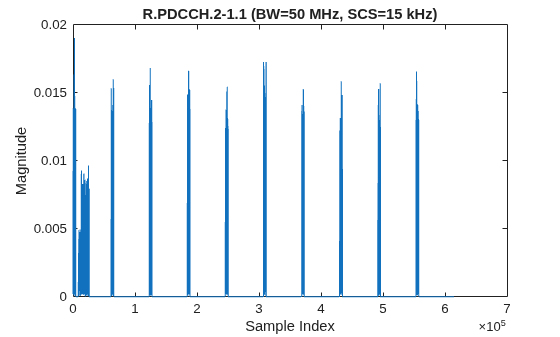
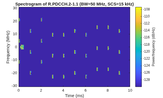
TS 38.101-5 Annex A.3.3 defines R.PDCCH RMCs for NTN UE receiver PDCCH demodulation performance testing. These tests evaluate downlink control information (DCI) detection performance under NTN fading channel conditions using the NTN-TDL-D channel model with 5 Hz Doppler. The R.PDCCH configurations define CORESET frequency and time resources, aggregation levels, and DCI formats. Scheduling is continuous, with every slot active. The waveform does not transmit PDSCH data because the tests evaluate only control-channel reception performance.
NTN UE PDCCH demodulation tests use these RMCs for:
PDCCH demodulation (TS 38.101-5 Section 8.4) - DCI missed detection probability at defined SNR
Tests cover aggregation levels 8 and 16 across different CORESET configurations
Supported R.PDCCH RMC Presets
You can view the list of available R.PDCCH presets using the RPDCCH property of the hNRNTNPresetConfig object.
FR1 15 kHz presets:
R.PDCCH.2-1.1 defines an aggregation level 8 PDCCH configuration with a full-band CORESET spanning one symbol for PDCCH demodulation testing.
R.PDCCH.2-1.2 defines an aggregation level 16 with full-band CORESET spanning 2 symbols for PDCCH demodulation testing.
FR1 30 kHz presets:
R.PDCCH.3-1.1 defines an aggregation level 8 with full-band CORESET spanning 1 symbol for PDCCH demodulation testing.
R.PDCCH.3-1.2 defines an aggregation level 16 with full-band CORESET spanning 2 symbols for PDCCH demodulation testing.
FR2 120 kHz presets:
R.PDCCH.1-1.1 defines an aggregation level 8 with full-band CORESET spanning 1 symbol for PDCCH demodulation testing.
R.PDCCH.1-1.2 defines an aggregation level 16 with full-band CORESET spanning 2 symbols for PDCCH demodulation testing.
rpdcchPresets = hNRNTNPresetConfig.RPDCCH
rpdcchPresets = 6×1 string
    "R.PDCCH.1-1.1"
    "R.PDCCH.1-1.2"
    "R.PDCCH.2-1.1"
    "R.PDCCH.2-1.2"
    "R.PDCCH.3-1.1"
    "R.PDCCH.3-1.2"
Set R.PDCCH RMC
Configure an R.PDCCH RMC preset by specifying the preset name using the hNRNTNPresetConfig object.
Optional name-value arguments include:
ChannelBandwidth- Channel bandwidth in MHz. When you specify this argument as[], the object uses the specification-defined value for the selected preset.SubcarrierSpacing- Subcarrier spacing in kHz. When you specify this argument as[], the object uses the specification-defined value for the selected preset.NCellID- Physical layer cell identity. The default value is 1.OCNG-false(default) ortrue. Set totrueto fill unused downlink PRBs with channel noise, as defined in TS 38.101-5 A.5.1.1.
presetName ="R.PDCCH.2-1.1"; channelBandwidth = []; % Channel bandwidth in MHz, [] represents default value from specification subcarrierSpacing = []; % Subcarrier spacing in kHz, [] represents default value from specification enableOCNG =
false; % Fill unused PRBs with OCNG, as defined in TS 38.101-5 A.5.1.1 % Create preset configuration ntnRPDCCH = hNRNTNPresetConfig(presetName, ... ChannelBandwidth=channelBandwidth, ... SubcarrierSpacing=subcarrierSpacing, ... OCNG=enableOCNG); % View the configured CORESET ntnRPDCCH.Carrier.CORESET{1}
ans =
  nrCORESETConfig with properties:

              CORESETID: 1
                  Label: 'CORESET1'
     FrequencyResources: [1 1 1 1 1 1 1 1 1 1 1 1 1 1 1 1 1 1 1 1 1 1 1 1 1 1 1 1 1 1 1 1 1 1 1 1 1 1 1 1 1 1 1 1 1]
               Duration: 1
          CCEREGMapping: 'interleaved'
          REGBundleSize: 2
        InterleaverSize: 3
             ShiftIndex: 0
    PrecoderGranularity: 'sameAsREG-bundle'
               RBOffset: []

   Read-only properties:
                   NCCE: 45
% View the configured PDCCH
ntnRPDCCH.Carrier.PDCCH{1}
ans =
nrWavegenPDCCHConfig with properties:
Enable: 1
Label: 'PDCCH1'
Power: 0
BandwidthPartID: 1
SearchSpaceID: 1
AggregationLevel: 8
AllocatedCandidate: 1
CCEOffset: []
SlotAllocation: 0
Period: 1
AntennaMapping: []
PrecodingMatrix: []
Coding: 1
DataBlockSize: 44
DataSource: 'PN9-ITU'
RNTI: 1
DMRSScramblingID: 2
DMRSPower: 0
Generate R.PDCCH RMC Waveform
Generate the baseband waveform using the nrWaveformGenerator function.
[rpdcchWaveform,rpdcchWaveInfo] = nrWaveformGenerator(ntnRPDCCH.Carrier);
Visualize R.PDCCH RMC Waveform
Plot the time-domain magnitude and spectrogram of the generated R.PDCCH waveform.
% Plot waveform magnitude
figure
plot(abs(rpdcchWaveform))
title(presetName + " (BW=" + ntnRPDCCH.Carrier.ChannelBandwidth + " MHz, SCS=" + ntnRPDCCH.Carrier.SCSCarriers{1}.SubcarrierSpacing + " kHz)")
xlabel("Sample Index")
ylabel("Magnitude")
% Plot spectrogram
sampleRate = rpdcchWaveInfo.ResourceGrids.Info.SampleRate;
nfft = rpdcchWaveInfo.ResourceGrids.Info.Nfft;
figure
spectrogram(rpdcchWaveform(:,1),ones(nfft,1),0,nfft,"centered",sampleRate,"yaxis",MinThreshold=-130)
title("Spectrogram of " + presetName + " (BW=" + ntnRPDCCH.Carrier.ChannelBandwidth + " MHz, SCS=" + ntnRPDCCH.Carrier.SCSCarriers{1}.SubcarrierSpacing + " kHz)")
Downlink FRC Waveform Generation
TS 38.101-5 Annex A.3.4 defines downlink (DL) receiver (Rx) FRCs for NTN UE receiver sensitivity and selectivity testing. The network transmits a known reference signal at a defined power level, and the UE must achieve a specified throughput percentage. DL Rx FRCs use transport-block-coded PDSCH with redundancy version 0, front-loaded mapping type A, DM-RS type 1 with 2 additional positions, and NTN-specific discontinuous slot scheduling.
TS 38.101-5 Tables A.3.4.1-x define these DL Rx FRC scheduling patterns.
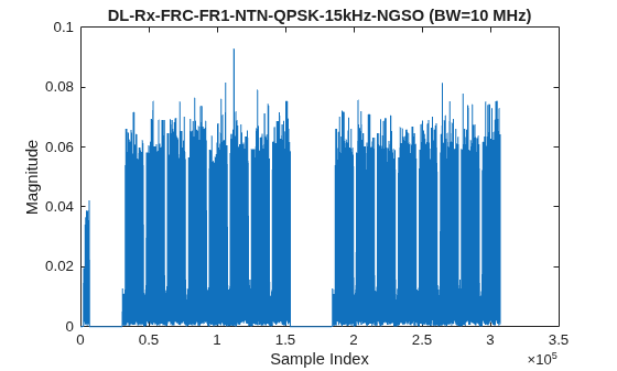
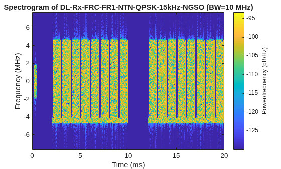
FR1 15 kHz NGSO uses a 20-slot scheduling period in which slots 2 through 9 and 12 through 19 are active, resulting in 16 active slots and 4 inactive slots per period.
FR1 15 kHz GSO uses a 320-slot scheduling period in which slots 2 through 9 and 12 through 19 are active, resulting in 16 active slots and 304 inactive slots per period.
FR1 30 kHz NGSO uses a 40-slot scheduling period in which slots 4 through 19 are active, resulting in 16 active slots and 24 inactive slots per period.
FR1 30 kHz GSO uses a 640-slot scheduling period in which slots 4 through 19 are active, resulting in 16 active slots and 624 inactive slots per period.
FR2 60 kHz and 120 kHz use a scheduling pattern in which a slot with index i is active when mod(i,5) equals 0, 1, or 2 for i >= 1, resulting in 3 active slots out of every 5 slots.
NTN UE receiver tests use these FRCs for:
Reference sensitivity testing defined in TS 38.101-5 Section 7.2, which verifies the minimum signal level required to achieve 95% throughput.
Maximum input level testing defined in Section 7.3, which evaluates UE performance at high received signal power.
Adjacent channel selectivity testing defined in Section 7.4, which evaluates receiver performance in the presence of an adjacent-channel interferer.
In-band blocking testing defined in Section 7.5, which evaluates receiver performance in the presence of an interferer within the operating band.
Out-of-band blocking testing defined in Section 7.6, which evaluates receiver performance in the presence of an interferer outside the operating band.
Spurious response testing defined in Section 7.7, which evaluates receiver performance in the presence of discrete spurious interferers.
Intermodulation testing defined in Section 7.8, which evaluates receiver performance in a two-tone interference scenario.
Supported Downlink FRC Presets
You can view the list of available FR1 and FR2 downlink FRC categories using the FR1DownlinkRxFRC and FR2DownlinkRxFRC properties of the hNRNTNPresetConfig object.
FR1 categories:
DL-Rx-FRC-FR1-NTN-QPSK-15kHz-NGSO defines a QPSK waveform with a code rate of 1/3 for 15 kHz subcarrier spacing in an NGSO deployment and supports reference sensitivity, adjacent channel selectivity, and blocking tests.
DL-Rx-FRC-FR1-NTN-64QAM-15kHz-NGSO defines a 64QAM waveform with a code rate of 3/4 for 15 kHz subcarrier spacing in an NGSO deployment and supports maximum input level and intermodulation tests.
DL-Rx-FRC-FR1-NTN-QPSK-15kHz-GSO defines a QPSK waveform with a code rate of 1/3 for 15 kHz subcarrier spacing in a GSO deployment and supports reference sensitivity testing.
DL-Rx-FRC-FR1-NTN-64QAM-15kHz-GSO defines a 64QAM waveform with a code rate of 3/4 for 15 kHz subcarrier spacing in a GSO deployment and supports maximum input level testing.
DL-Rx-FRC-FR1-NTN-QPSK-30kHz-NGSO defines a QPSK waveform with a code rate of 1/3 for 30 kHz subcarrier spacing in an NGSO deployment and supports reference sensitivity testing.
DL-Rx-FRC-FR1-NTN-64QAM-30kHz-NGSO defines a 64QAM waveform with a code rate of 3/4 for 30 kHz subcarrier spacing in an NGSO deployment and supports maximum input level testing.
DL-Rx-FRC-FR1-NTN-QPSK-30kHz-GSO defines a QPSK waveform with a code rate of 1/3 for 30 kHz subcarrier spacing in a GSO deployment and supports reference sensitivity testing.
DL-Rx-FRC-FR1-NTN-64QAM-30kHz-GSO defines a 64QAM waveform with a code rate of 3/4 for 30 kHz subcarrier spacing in a GSO deployment and supports maximum input level testing.
FR2 categories:
DL-Rx-FRC-FR2-NTN-QPSK-60kHz defines a QPSK waveform with a code rate of 1/3 for 60 kHz subcarrier spacing and supports reference sensitivity testing.
DL-Rx-FRC-FR2-NTN-16QAM-60kHz defines a 16QAM waveform with a code rate of 0.48 for 60 kHz subcarrier spacing and supports maximum input level testing.
DL-Rx-FRC-FR2-NTN-64QAM-60kHz defines a 64QAM waveform with a code rate of 1/2 for 60 kHz subcarrier spacing and supports blocking and intermodulation tests.
DL-Rx-FRC-FR2-NTN-QPSK-120kHz defines a QPSK waveform with a code rate of 1/3 for 120 kHz subcarrier spacing and supports reference sensitivity testing.
DL-Rx-FRC-FR2-NTN-16QAM-120kHz defines a 16QAM waveform with a code rate of 0.48 for 120 kHz subcarrier spacing and supports maximum input level testing.
DL-Rx-FRC-FR2-NTN-64QAM-120kHz defines a 64QAM waveform with a code rate of 1/2 for 120 kHz subcarrier spacing and supports blocking testing.
fr1DLRxFRC = hNRNTNPresetConfig.FR1DownlinkRxFRC
fr1DLRxFRC = 8×1 string
    "DL-Rx-FRC-FR1-NTN-QPSK-15kHz-NGSO"
    "DL-Rx-FRC-FR1-NTN-QPSK-15kHz-GSO"
    "DL-Rx-FRC-FR1-NTN-64QAM-15kHz-NGSO"
    "DL-Rx-FRC-FR1-NTN-64QAM-15kHz-GSO"
    "DL-Rx-FRC-FR1-NTN-QPSK-30kHz-NGSO"
    "DL-Rx-FRC-FR1-NTN-QPSK-30kHz-GSO"
    "DL-Rx-FRC-FR1-NTN-64QAM-30kHz-NGSO"
    "DL-Rx-FRC-FR1-NTN-64QAM-30kHz-GSO"
fr2DLRxFRC = hNRNTNPresetConfig.FR2DownlinkRxFRC
fr2DLRxFRC = 6×1 string
    "DL-Rx-FRC-FR2-NTN-QPSK-60kHz"
    "DL-Rx-FRC-FR2-NTN-16QAM-60kHz"
    "DL-Rx-FRC-FR2-NTN-64QAM-60kHz"
    "DL-Rx-FRC-FR2-NTN-QPSK-120kHz"
    "DL-Rx-FRC-FR2-NTN-16QAM-120kHz"
    "DL-Rx-FRC-FR2-NTN-64QAM-120kHz"
Set Downlink FRC
Configure a downlink FRC preset using either a named category or parametric construction with the hNRNTNPresetConfig object.
Named category - Specify the full category name directly.
Parametric - Specify "DL-Rx-FRC-NTN" with the following required name-value arguments:
FrequencyRange- "FR1"or "FR2"MCS- Modulation and coding scheme string. FR1 supports "QPSK 1/3"and "64QAM 3/4", while FR2 supports "QPSK 1/3", "16QAM 0.48", and "64QAM 1/2".SubcarrierSpacing- Subcarrier spacing in kHz. FR1 supports 15 kHz or 30 kHz and FR2 supports 60 kHz or 120 kHz.OrbitType-"NGSO"or"GSO". This argument is required for FR1 and ignored for FR2.
Optional name-value arguments for named category or parametric construction:
ChannelBandwidth- Channel bandwidth in MHz. When you specify this argument as[], the object uses 10 MHz for FR1 and 100 MHz for FR2.NCellID- Physical layer cell identity. The default value is 1.OCNG-false(default) ortrue. Set totrueto fill unused downlink PRBs with channel noise, as defined in TS 38.101-5 A.5.1.1.
frequencyRange ="FR1"; % Frequency range ("FR1","FR2") mcs =
"QPSK 1/3"; % MCS ("QPSK 1/3","64QAM 3/4" for FR1; "QPSK 1/3","16QAM 0.48","64QAM 1/2" for FR2) subcarrierSpacing = 15; % Subcarrier spacing in kHz (15 kHz or 30 kHz for FR1 and 60 kHz or 120 kHz for FR2) orbitType =
"NGSO"; % Orbit type ("NGSO","GSO") - required for FR1, ignored for FR2 channelBandwidth = 10; % Channel bandwidth in MHz, [] represents 10 MHz for FR1 and 100 MHz for FR2 % Create preset using parametric construction ntnDLRxFRC = hNRNTNPresetConfig("DL-Rx-FRC-NTN", ... FrequencyRange=frequencyRange, ... MCS=mcs, ... SubcarrierSpacing=subcarrierSpacing, ... OrbitType=orbitType, ... ChannelBandwidth=channelBandwidth); % View the configured preset name and PDSCH ntnDLRxFRC.PresetName
ans =
"DL-Rx-FRC-FR1-NTN-QPSK-15kHz-NGSO"
ntnDLRxFRC.Carrier.PDSCH{1}ans =
nrWavegenPDSCHConfig with properties:
Enable: 1
Label: 'PDSCH1'
Power: 0
BandwidthPartID: 1
Modulation: 'QPSK'
NumLayers: 1
MappingType: 'A'
ReservedPRB: {[1×1 nrPDSCHReservedConfig]}
ReservedCORESET: []
SymbolAllocation: [2 12]
SlotAllocation: [2 3 4 5 6 7 8 9 12 13 14 15 16 17 18 19]
Period: 20
PRBSet: [0 1 2 3 4 5 6 7 8 9 10 11 12 13 14 15 16 17 18 19 20 21 22 23 24 25 26 27 28 29 30 31 32 33 34 35 36 37 38 39 40 41 42 43 44 45 46 47 48 49 50 51]
PRBSetType: 'VRB'
VRBToPRBInterleaving: 0
AntennaMapping: []
PrecodingMatrix: []
NID: []
RNTI: 0
Coding: 1
TargetCodeRate: 0.3008
TBScaling: 1
XOverhead: 0
LimitedBufferRateMatching: 1
MaxNumLayers: 8
MCSTable: 'qam64'
RVSequence: 0
DataSource: 'PN9-ITU'
DMRS: [1×1 nrPDSCHDMRSConfig]
DMRSPower: 3
EnablePTRS: 0
Read-only properties:
NumCodewords: 1
TransportBlockSize: 3368
Generate Downlink FRC Waveform
Generate the baseband waveform using the nrWaveformGenerator function.
[dlRxWaveform,dlRxWaveInfo] = nrWaveformGenerator(ntnDLRxFRC.Carrier);
Visualize Downlink FRC Waveform
Plot the time-domain magnitude and spectrogram showing the discontinuous NTN slot scheduling pattern.
% Plot waveform magnitude
figure
plot(abs(dlRxWaveform))
title(ntnDLRxFRC.PresetName + " (BW=" + ntnDLRxFRC.Carrier.ChannelBandwidth + " MHz)")
xlabel("Sample Index")
ylabel("Magnitude")
% Plot spectrogram
sampleRate = dlRxWaveInfo.ResourceGrids.Info.SampleRate;
nfft = dlRxWaveInfo.ResourceGrids.Info.Nfft;
figure
spectrogram(dlRxWaveform(:,1),ones(nfft,1),0,nfft,"centered",sampleRate,"yaxis",MinThreshold=-130)
title("Spectrogram of " + ntnDLRxFRC.PresetName + " (BW=" + ntnDLRxFRC.Carrier.ChannelBandwidth + " MHz)")
Uplink RMC Waveform Generation
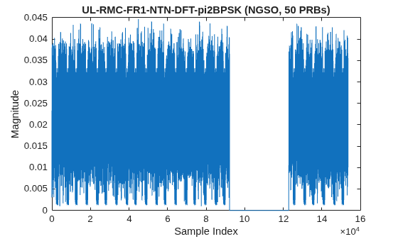
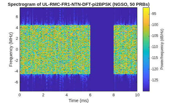
TS 38.101-5 Annex A.4 defines uplink (UL) RMCs for NTN UE transmitter conformance testing. These RMCs define uplink waveforms with specific waveform types and modulation schemes for evaluating UE transmitter performance. The specification defines both DFT-s-OFDM waveforms with transform precoding enabled and CP-OFDM waveforms with transform precoding disabled. Supported modulation schemes include pi/2-BPSK, QPSK, 16QAM, and 64QAM. The pi/2-BPSK modulation scheme provides the lowest peak-to-average power ratio (PAPR) and is specific to NTN operation. All UL RMCs use full-slot mapping type A with a symbol allocation of [0 14], resulting in 11 data-bearing OFDM symbols per slot after excluding three DM-RS symbols.
UL RMCs use NTN-specific discontinuous scheduling patterns defined in TS 38.101-5 Tables A.2.1-1 and A.2.1-2 for NGSO and GSO respectively.
NGSO 15 kHz uses a 10-slot scheduling period in which slots 0 through 5 and 8 through 9 are active, resulting in 8 active slots out of every 10 slots.
NGSO 30 kHz uses a 40-slot scheduling period in which slots 0 through 9 and 34 through 39 are active, resulting in 16 active slots out of every 40 slots.
GSO 15 kHz uses a 320-slot scheduling period in which slots 262 through 269 and 272 through 279 are active, resulting in 16 active slots out of every 320 slots.
GSO 30 kHz uses a 640-slot scheduling period in which slots 522 through 537 are active, resulting in 16 active slots out of every 640 slots.
FR2 configurations use the same NGSO and GSO scheduling patterns with subcarrier spacings of 60 kHz and 120 kHz.
NTN UE transmitter conformance tests use these RMCs for:
Maximum output power testing defined in TS 38.101-5 Section 6.2.
Maximum power reduction (MPR) testing defined in Section 6.2.2, which evaluates the allowed transmit-power backoff for high-PAPR waveforms.
EVM testing defined in Section 6.4.2, which evaluates transmit signal quality for each modulation scheme.
Carrier leakage and in-band emissions testing defined in Section 6.4.2.
ACLR testing defined in Section 6.6.2.
Spectrum emission mask testing defined in Section 6.6.1.
Spurious emissions testing defined in Section 6.6.3.
Supported Uplink RMC Presets
You can view the list of available FR1 and FR2 uplink RMC categories using the FR1UplinkRMC and FR2UplinkRMC properties of the hNRNTNPresetConfig object.
FR1 DFT-s-OFDM (transform precoding):
UL-RMC-FR1-NTN-DFT-pi2BPSK defines a DFT-s-OFDM waveform with pi/2-BPSK modulation and supports MPR and EVM testing.
UL-RMC-FR1-NTN-DFT-QPSK defines a DFT-s-OFDM waveform with QPSK modulation and supports EVM, ACLR, and spectrum emission testing.
UL-RMC-FR1-NTN-DFT-16QAM defines a DFT-s-OFDM waveform with 16QAM modulation and supports EVM and MPR testing.
UL-RMC-FR1-NTN-DFT-64QAM defines a DFT-s-OFDM waveform with 64QAM modulation and supports EVM and MPR testing.
FR1 CP-OFDM:
UL-RMC-FR1-NTN-CPOFDM-QPSK defines a CP-OFDM waveform with QPSK modulation and supports EVM and ACLR testing.
UL-RMC-FR1-NTN-CPOFDM-16QAM defines a CP-OFDM waveform with 16QAM modulation and supports EVM and MPR testing.
UL-RMC-FR1-NTN-CPOFDM-64QAM defines a CP-OFDM waveform with 64QAM modulation and supports EVM and MPR testing.
FR2 DFT-s-OFDM:
UL-RMC-FR2-NTN-DFT-pi2BPSK defines a DFT-s-OFDM waveform with pi/2-BPSK modulation and supports MPR and EVM testing.
UL-RMC-FR2-NTN-DFT-QPSK defines a DFT-s-OFDM waveform with QPSK modulation and supports EVM and ACLR testing.
UL-RMC-FR2-NTN-DFT-16QAM defines a DFT-s-OFDM waveform with 16QAM modulation and supports EVM and MPR testing.
UL-RMC-FR2-NTN-DFT-64QAM defines a DFT-s-OFDM waveform with 64QAM and supports EVM and MPR testing.
FR2 CP-OFDM:
UL-RMC-FR2-NTN-CPOFDM-QPSK defines a CP-OFDM waveform with QPSK modulation and supports EVM testing.
UL-RMC-FR2-NTN-CPOFDM-16QAM defines a CP-OFDM waveform with 16QAM modulation and supports EVM and MPR testing.
UL-RMC-FR2-NTN-CPOFDM-64QAM defines a CP-OFDM waveform with 64QAM modulation and supports EVM and MPR testing.
fr1UplinkRMC = hNRNTNPresetConfig.FR1UplinkRMC
fr1UplinkRMC = 7×1 string
    "UL-RMC-FR1-NTN-DFT-pi2BPSK"
    "UL-RMC-FR1-NTN-DFT-QPSK"
    "UL-RMC-FR1-NTN-DFT-16QAM"
    "UL-RMC-FR1-NTN-DFT-64QAM"
    "UL-RMC-FR1-NTN-CPOFDM-QPSK"
    "UL-RMC-FR1-NTN-CPOFDM-16QAM"
    "UL-RMC-FR1-NTN-CPOFDM-64QAM"
fr2UplinkRMC = hNRNTNPresetConfig.FR2UplinkRMC
fr2UplinkRMC = 7×1 string
    "UL-RMC-FR2-NTN-DFT-pi2BPSK"
    "UL-RMC-FR2-NTN-DFT-QPSK"
    "UL-RMC-FR2-NTN-DFT-16QAM"
    "UL-RMC-FR2-NTN-DFT-64QAM"
    "UL-RMC-FR2-NTN-CPOFDM-QPSK"
    "UL-RMC-FR2-NTN-CPOFDM-16QAM"
    "UL-RMC-FR2-NTN-CPOFDM-64QAM"
Set Uplink RMC
Configure an uplink RMC preset using either a named category or parametric construction with the hNRNTNPresetConfig object.
Named category - Specify the full category name.
Parametric - Specify "UL-RMC-NTN" with the following required name-value arguments:
FrequencyRange- "FR1"or "FR2"Waveform-"DFT-s-OFDM"or"CP-OFDM"Modulation-"pi/2-BPSK","QPSK","16QAM", or"64QAM"
Optional name-value arguments for named category or parametric construction:
ChannelBandwidth- Channel bandwidth in MHz. When you specify this argument as[], the object uses 10 MHz for FR1 and 100 MHz for FR2.SubcarrierSpacing- Subcarrier spacing in kHz. When you specify this argument as[], the object uses 15 kHz for FR1 and 120 kHz for FR2.LCRB- Number of allocated PRBs. When you specify this argument as[], the object uses the number of resource blocks that span the full channel bandwidth for the specified subcarrier spacing. For DFT-s-OFDM, the value must satisfy the criterion .OrbitType- "NGSO"(default) or "GSO".
frequencyRange ="FR1"; % Frequency range ("FR1","FR2") waveformType =
"DFT-s-OFDM"; % Waveform type ("DFT-s-OFDM","CP-OFDM") modulation =
"pi/2-BPSK"; % Modulation ("pi/2-BPSK","QPSK","16QAM","64QAM") channelBandwidth = []; % Channel bandwidth in MHz, [] represents 10 MHz for FR1 and 100 MHz for FR2 subcarrierSpacing = []; % Subcarrier spacing in kHz, [] represents 15 kHz for FR1 and 120 kHz for FR2 lcrb = []; % Allocated PRBs (must be 2^a*3^b*5^c for DFT-s-OFDM) or [] for full bandwidth orbitType =
"NGSO"; % Orbit type ("NGSO","GSO") - determines active slot pattern % Create preset using parametric construction ntnULRMC = hNRNTNPresetConfig("UL-RMC-NTN", ... FrequencyRange=frequencyRange, ... Waveform=waveformType, ... Modulation=modulation, ... ChannelBandwidth=channelBandwidth, ... SubcarrierSpacing=subcarrierSpacing, ... LCRB=lcrb, ... OrbitType=orbitType); % View the configured preset name and PUSCH ntnULRMC.PresetName
ans =
"UL-RMC-FR1-NTN-DFT-pi2BPSK"
ntnULRMC.Carrier.PUSCH{1}ans =
nrWavegenPUSCHConfig with properties:
Enable: 1
Label: 'PUSCH1'
Power: 0
BandwidthPartID: 1
Modulation: 'pi/2-BPSK'
NumLayers: 1
MappingType: 'A'
SymbolAllocation: [0 14]
SlotAllocation: [0 1 2 3 4 5 8 9]
Period: 10
PRBSet: [1 2 3 4 5 6 7 8 9 10 11 12 13 14 15 16 17 18 19 20 21 22 23 24 25 26 27 28 29 30 31 32 33 34 35 36 37 38 39 40 41 42 43 44 45 46 47 48 49 50]
TransformPrecoding: 1
TransmissionScheme: 'nonCodebook'
FrequencyHopping: 'neither'
Interlacing: 0
AntennaMapping: []
PrecodingMatrix: []
NID: []
RNTI: 1
NRAPID: []
Coding: 1
TargetCodeRate: 0.2344
XOverhead: 0
LimitedBufferRateMatching: 0
RVSequence: [0 2 3 1]
DataSource: 'PN9-ITU'
EnableACK: 0
EnableCSI1: 0
EnableCGUCI: 0
DMRS: [1×1 nrPUSCHDMRSConfig]
DMRSPower: 0
EnablePTRS: 0
Read-only properties:
NumCodewords: 1
TransportBlockSize: 1544
Generate Uplink RMC Waveform
Generate the baseband waveform using the nrWaveformGenerator function.
[ulRMCWaveform,ulRMCWaveInfo] = nrWaveformGenerator(ntnULRMC.Carrier);
Visualize Uplink RMC Waveform
Plot the time-domain magnitude and spectrogram showing the NGSO discontinuous slot scheduling pattern.
% Plot waveform magnitude
figure
plot(abs(ulRMCWaveform))
title(ntnULRMC.PresetName + " (" + orbitType + ", " + numel(ntnULRMC.Carrier.PUSCH{1}.PRBSet) + " PRBs)")
xlabel("Sample Index")
ylabel("Magnitude")
% Plot spectrogram
sampleRate = ulRMCWaveInfo.ResourceGrids.Info.SampleRate;
nfft = ulRMCWaveInfo.ResourceGrids.Info.Nfft;
figure
spectrogram(ulRMCWaveform(:,1),ones(nfft,1),0,nfft,"centered",sampleRate,"yaxis",MinThreshold=-130)
title("Spectrogram of " + ntnULRMC.PresetName + " (" + orbitType + ", " + numel(ntnULRMC.Carrier.PUSCH{1}.PRBSet) + " PRBs)")
Uplink FRC Waveform Generation
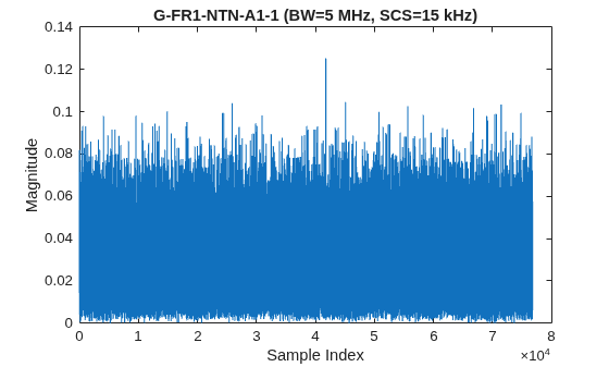
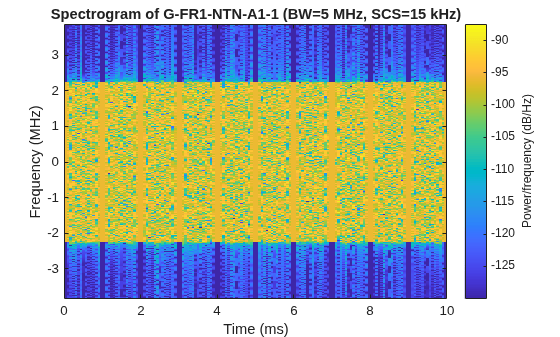
TS 38.108 Annex A defines UL FRCs for NTN satellite base station (SAN) receiver conformance testing. They specify known uplink signals that the SAN must decode at specified throughput levels. UL FRC waveforms contain transport-coded PUSCH with redundancy version 0. Each preset fixes the PRB allocation from the spec table. Each slot uses a symbol allocation of [0 14] for full-slot mapping type A. Scheduling is continuous with all slots active, as TS 38.108 defines only per-slot PUSCH parameters with no inactive slot pattern.
UL FRC categories define different modulation and rate combinations for different SAN receiver tests:
Annex A1 defines QPSK CP-OFDM waveforms with a code rate of 308/1024 for reference sensitivity testing, which measures the minimum detectable signal level required to achieve 95% throughput (Section 7.2).
Annex A2 defines 16QAM CP-OFDM waveforms with a code rate of 658/1024 for dynamic range testing, which evaluates performance in the presence of an interfering signal (Section 7.3).
Annex A3 defines QPSK CP-OFDM and DFT-s-OFDM waveforms with a code rate of 308/1024 for PUSCH demodulation performance testing (Section 8.2).
Annex A3A defines QPSK CP-OFDM and DFT-s-OFDM waveforms with a code rate of 99/1024 for PUSCH demodulation performance testing at low spectral efficiency (Section 8.2).
Annex A5 defines QPSK CP-OFDM and DFT-s-OFDM waveforms with a code rate of 193/1024 for FR2 PUSCH demodulation performance testing (Section 8.2).
Annex A6 defines 16QAM CP-OFDM waveforms with a code rate of 434/1024 for FR2 PUSCH demodulation performance testing at higher spectral efficiency (Section 8.2).
Supported Uplink FRC Presets
You can view the list of available FR1 and FR2 uplink FRC presets using the FR1UplinkFRC and FR2UplinkFRC properties of the hNRNTNPresetConfig object.
FR1 presets:
G-FR1-NTN-A1-1 to A1-12 define CP-OFDM waveforms with QPSK modulation and a code rate of 308/1024 and support SAN reference sensitivity testing.
G-FR1-NTN-A2-1 to A2-7 define CP-OFDM waveforms with 16QAM modulation and a code rate of 658/1024 and support SAN dynamic range testing.
G-FR1-NTN-A3-1 to A3-8 define CP-OFDM and DFT-s-OFDM waveforms with QPSK modulation and a code rate of 308/1024 and support PUSCH demodulation performance testing.
G-FR1-NTN-A3A-1 to A3A-4 define CP-OFDM and DFT-s-OFDM waveforms with QPSK modulation and a code rate of 99/1024 and support PUSCH demodulation performance testing at low spectral efficiency.
FR2 presets:
G-FR2-NTN-A1-1 to A1-3 define CP-OFDM waveforms with QPSK modulation and a code rate of 308/1024 and support SAN reference sensitivity testing.
G-FR2-NTN-A3A-1 defines a CP-OFDM waveform with QPSK modulation and a code rate of 99/1024 and supports PUSCH demodulation performance testing.
G-FR2-NTN-A5-1 to A5-2 define CP-OFDM and DFT-s-OFDM waveforms with QPSK modulation and a code rate of 193/1024 and support PUSCH demodulation performance testing.
G-FR2-NTN-A6-1 defines a CP-OFDM waveform with 16QAM modulation and a code rate of 434/1024 and supports PUSCH demodulation performance testing.
fr1UplinkFRC = hNRNTNPresetConfig.FR1UplinkFRC
fr1UplinkFRC = 31×1 string
    "G-FR1-NTN-A1-1"
    "G-FR1-NTN-A1-2"
    "G-FR1-NTN-A1-3"
    "G-FR1-NTN-A1-4"
    "G-FR1-NTN-A1-5"
    "G-FR1-NTN-A1-6"
    "G-FR1-NTN-A1-7"
    "G-FR1-NTN-A1-8"
    "G-FR1-NTN-A1-9"
    "G-FR1-NTN-A1-10"
    "G-FR1-NTN-A1-11"
    "G-FR1-NTN-A1-12"
    "G-FR1-NTN-A2-1"
    "G-FR1-NTN-A2-2"
    "G-FR1-NTN-A2-3"
    "G-FR1-NTN-A2-4"
    "G-FR1-NTN-A2-5"
    "G-FR1-NTN-A2-6"
    "G-FR1-NTN-A2-7"
    "G-FR1-NTN-A3-1"
    "G-FR1-NTN-A3-2"
    "G-FR1-NTN-A3-3"
    "G-FR1-NTN-A3-4"
    "G-FR1-NTN-A3-5"
    "G-FR1-NTN-A3-6"
    "G-FR1-NTN-A3-7"
    "G-FR1-NTN-A3-8"
    "G-FR1-NTN-A3A-1"
    "G-FR1-NTN-A3A-2"
    "G-FR1-NTN-A3A-3"
      ⋮
fr2UplinkFRC = hNRNTNPresetConfig.FR2UplinkFRC
fr2UplinkFRC = 7×1 string
    "G-FR2-NTN-A1-1"
    "G-FR2-NTN-A1-2"
    "G-FR2-NTN-A1-3"
    "G-FR2-NTN-A3A-1"
    "G-FR2-NTN-A5-1"
    "G-FR2-NTN-A5-2"
    "G-FR2-NTN-A6-1"
Set Uplink FRC
Configure an uplink FRC preset by specifying the preset name using the hNRNTNPresetConfig object.
Optional name-value arguments include:
ChannelBandwidth- Channel bandwidth in MHz. When you specify the argument as[], the object selects the smallest channel bandwidth that accommodates the FRC's allocated PRBs, with a minimum bandwidth of 5 MHz.SubcarrierSpacing- Subcarrier spacing in kHz. When you specify the argument as[], the object uses the specification-defined value for the selected preset.NCellID- Physical layer cell identity. The default value is 1.
presetName ="G-FR1-NTN-A1-1"; channelBandwidth = []; % Channel bandwidth in MHz, [] represents the smallest channel bandwidth that accommodates the FRC allocated PRBs (minimum 5 MHz) subcarrierSpacing = []; % Subcarrier spacing in kHz, [] represents default value from specification % Create preset configuration ntnULFRC = hNRNTNPresetConfig(presetName, ... ChannelBandwidth=channelBandwidth, ... SubcarrierSpacing=subcarrierSpacing); % View the configured PUSCH ntnULFRC.Carrier.PUSCH{1}
ans =
  nrWavegenPUSCHConfig with properties:

                       Enable: 1
                        Label: 'PUSCH sequence for G-FR1-A1-1'
                        Power: 0
              BandwidthPartID: 1
                   Modulation: 'QPSK'
                    NumLayers: 1
                  MappingType: 'A'
             SymbolAllocation: [0 14]
               SlotAllocation: [0 1 2 3 4 5 6 7 8 9]
                       Period: 10
                       PRBSet: [0 1 2 3 4 5 6 7 8 9 10 11 12 13 14 15 16 17 18 19 20 21 22 23 24]
           TransformPrecoding: 0
           TransmissionScheme: 'codebook'
              NumAntennaPorts: 1
                         TPMI: 0
             FrequencyHopping: 'neither'
                  Interlacing: 0
               AntennaMapping: []
                          NID: []
                         RNTI: 1
                       NRAPID: []
                       Coding: 1
               TargetCodeRate: 0.3008
                    XOverhead: 0
    LimitedBufferRateMatching: 0
                   RVSequence: 0
                   DataSource: 'PN9-ITU'
                    EnableACK: 0
                   EnableCSI1: 0
                  EnableCGUCI: 0
                         DMRS: [1×1 nrPUSCHDMRSConfig]
                    DMRSPower: 3
                   EnablePTRS: 0

   Read-only properties:
                 NumCodewords: 1
           TransportBlockSize: 2152
Generate Uplink FRC Waveform
Generate the baseband waveform using the nrWaveformGenerator function.
[ulFRCWaveform,ulFRCWaveInfo] = nrWaveformGenerator(ntnULFRC.Carrier);
Visualize Uplink FRC Waveform
Plot the time-domain magnitude and spectrogram of the generated uplink FRC waveform.
% Plot waveform magnitude
figure
plot(abs(ulFRCWaveform))
title(presetName + " (BW=" + ntnULFRC.Carrier.ChannelBandwidth + " MHz, SCS=" + ntnULFRC.Carrier.SCSCarriers{1}.SubcarrierSpacing + " kHz)")
xlabel("Sample Index")
ylabel("Magnitude")
% Plot spectrogram
sampleRate = ulFRCWaveInfo.ResourceGrids.Info.SampleRate;
nfft = ulFRCWaveInfo.ResourceGrids.Info.Nfft;
figure
spectrogram(ulFRCWaveform(:,1),ones(nfft,1),0,nfft,"centered",sampleRate,"yaxis",MinThreshold=-130)
title("Spectrogram of " + presetName + " (BW=" + ntnULFRC.Carrier.ChannelBandwidth + " MHz, SCS=" + ntnULFRC.Carrier.SCSCarriers{1}.SubcarrierSpacing + " kHz)")
Further Exploration
You can use these options to further customize NTN preset waveforms.
Named downlink FRC presets - Specify the full preset name directly, for example, "DL-Rx-FRC-FR1-NTN-QPSK-15kHz-NGSO", instead of constructing the preset from individual parameters. You can optionally specify the
ChannelBandwidthandSubcarrierSpacingarguments.Named uplink RMC presets - Specify the full preset name directly, for example, "UL-RMC-FR1-NTN-DFT-pi2BPSK". You can optionally specify the
ChannelBandwidth,SubcarrierSpacing,LCRB, andOrbitTypearguments.HD-FDD operation - Set the
DuplexModeargument toHD-FDDwhen creating an R.PDSCH preset. The configuration creates two PDSCH allocations: one for normal slots with a symbol allocation of [2 12] and one for guard-time slots with a symbol allocation of [6 8] to accommodate UE transmit-receive switching.GSO scheduling - Set the
OrbitTypeargument toGSOwhen creating an uplink RMC or downlink FRC preset. The resulting waveform uses sparse slot scheduling with long scheduling periods, such as 320 or 640 slots, to accommodate the longer round-trip delay of geostationary satellite links.Custom LCRB allocation - Set the
LCRBargument to specify a custom number of allocated PRBs instead of using the default full-bandwidth allocation for uplink RMC presets.Carrier configuration customization - Access the
Carrierproperty after creating the preset to modify the underlying nrDLCarrierConfig or nrULCarrierConfig object. For custom test scenarios, you can modify properties such asNCellID,NumSubframes, slot allocation and period of channel under test.
Supporting Files
The example uses these supporting files:
hNRNTNPresetConfig.m- Creates NTN preset waveform configurations with aCarrierproperty for use with thenrWaveformGeneratorfunctionhNRReferenceWaveformGenerator.m- Provides reference waveform generation utilities used by the preset configuration helperNTNPDSCHRMCDefinitions.m- Defines R.PDSCH RMC parameters from TS 38.101-5 Annex A.3.2NTNPDCCHRMCDefinitions.m- Defines R.PDCCH RMC parameters from TS 38.101-5 Annex A.3.3NTNDownlinkRxFRCDefinitions.m- Defines downlink FRC parameters from TS 38.101-5 Annex A.3.4NTNUplinkRMCDefinitions.m- Defines uplink RMC parameters from TS 38.101-5 Annex A.4NTNUplinkFRCDefinitions.m- Defines uplink FRC parameters from TS 38.108 Annex ANTNSchedulingDefinitions.m- Defines NTN orbit-dependent slot scheduling patterns from TS 38.101-5 Tables A.2.1-1 and A.2.1-2
References
[1] 3rd Generation Partnership Project (3GPP). 3GPP TS 38.181. "NR; Satellite Access Node (NR-SAN) conformance testing Part 1: Conducted conformance testing." 3rd Generation Partnership Project; Technical Specification Group Radio Access Network.
[2] 3rd Generation Partnership Project (3GPP). 3GPP TS 38.101-5. "NR; User Equipment (UE) radio transmission and reception; Part 5: Satellite access." 3rd Generation Partnership Project; Technical Specification Group Radio Access Network.
[3] 3rd Generation Partnership Project (3GPP). 3GPP TS 38.108. "NR; Satellite Access Node (NR-SAN) radio transmission and reception." 3rd Generation Partnership Project; Technical Specification Group Radio Access Network.

