Carrier Aggregation in 5G System-Level Simulation
R2026bCarrier aggregation enables a user equipment (UE) node to simultaneously transmit and receive data on multiple component carriers (CCs), increasing the effective bandwidth, as shown in this figure.
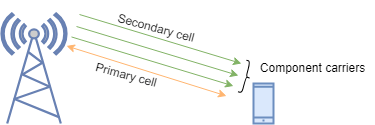
5G New Radio (NR) uses carrier aggregation to utilize a contiguous or fragmented spectrum across one or more frequency bands. This topic provides a brief overview of key aspects of CA, including component carriers, duplex modes, aggregation types, and primary and secondary carriers. It also summarizes the carrier aggregation capabilities available for configuring and simulating CA in the 5G system-level simulation.
Key Components of Carrier Aggregation
Component carriers form the foundation of carrier aggregation. A carrier occupies a contiguous block of spectrum with a defined bandwidth and center frequency and carries signals for transmission. A CC is a carrier that forms part of an aggregated bandwidth. Each CC contributes its spectrum to the total bandwidth available to the UE node.
5G NR supports aggregation of up to 16 component carriers, depending on UE capability.
Carriers separate downlink and uplink transmissions by using duplexing. Frequency division duplex (FDD) allocates separate frequency bands for downlink and uplink and enables simultaneous transmission and reception. Time division duplex (TDD) uses a single frequency band and separates downlink and uplink transmissions in time by using slot configuration. Carrier Aggregation supports both duplex modes. The 5G system-level simulation aggregates carriers that operate under the same duplex mode.
Carrier aggregation combines multiple component carriers to increase the effective bandwidth available to the UE node. The UE node processes multiple CCs in parallel and can transmit or receive data on one or more carriers simultaneously. The scheduler allocates resources for each CC and coordinates them at the medium access control (MAC) layer. The achieved throughput depends on:
The capability of the UE node to support multiple CCs
Signal quality on each CC
During carrier aggregation, each CC:
Allocates resources independently for the downlink and uplink
Performs link adaptation based on channel conditions
Supports Hybrid Automatic Repeat Request (HARQ) processes independently
Types of Carrier Aggregation
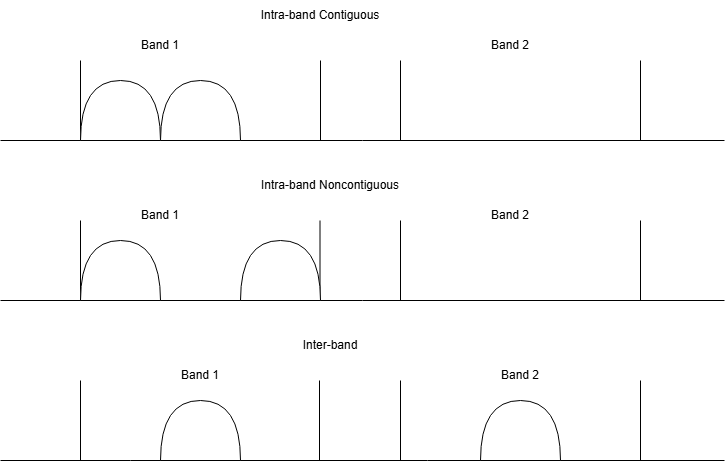
The three types of carrier aggregation are intra-band contiguous, intra-band noncontiguous, and inter-band. This image shows how the frequency relationship between the component carriers varies based on the type of carrier aggregation:
Intra-Band Carrier Aggregation
Intra-band contiguous carrier aggregation aggregates carriers that occupy adjacent frequency blocks within the same band. The combined spectrum appears continuous, but each carrier remains logically separate. For an example of intra-band contiguous aggregation, see Create Component Carrier Objects for Intra-Band Contiguous Aggregation.
Intra-Band Non-Contiguous Aggregation
Intra-band non-contiguous carrier aggregation aggregates carriers in the same band that are separated by frequency gaps. This configuration enables efficient use of fragmented spectrum in a band. For an example of intra-band non-contiguous aggregation, see Create Component Carrier Objects for Intra-Band Noncontiguous Aggregation.
Inter-Band Carrier Aggregation
Inter-band CA aggregates carriers from different frequency bands. This configuration provides flexibility in combining carriers with different propagation characteristics. For an example of inter-band aggregation, see Create Component Carrier Objects for Inter-Band Aggregation.
Primary Cell and Secondary Cells
In carrier aggregation, the component carriers can be the primary cell (PCell) or a secondary cell (SCell).
Primary Cell
The PCell anchors the UE connection to the gNB. The PCell:
Establishes the initial connection when the UE node connects to the gNB
Carries control packets, such as DL assignments, UL grants, physical downlink shared channel feedback, and channel state information report, and buffer status reports (BSRs) on the UE primary carrier.
The UE maintains continuous operation on the PCell.
Secondary Cells
The network configures additional component carriers as SCells. These cells:
Extend the available bandwidth
Primarily carry user-plane data
Activate and deactivate dynamically based on traffic demand and channel conditions
A UE node depends on the PCell for control-plane operation and uses SCells to increase throughput.
How to Enable Carrier Aggregation in 5G System-Level-Simulations
To enable carrier aggregation in a 5G system-level simulation, follow these steps:
Configure the component carriers by using the
nrComponentCarrierConfigobject. For more information about how to configure intra-band contiguous, intra-band non-contiguous, and inter-band aggregation for TDD and FDD modes with theCarrierFrequencyproperty andNumContiguousCarriersname-value argument, see Types of Carrier Aggregation and How to Configure Them.Configure the gNB node by using the
nrGNBobject. Assign the component carriers to the gNB node by using theComponentCarrierConfigproperty of thenrGNBobject.Configure the scheduler by using the
configureSchedulerfunction of thenrGNBobject. The scheduler independently allocates the downlink and uplink resources on each CC by using slot-based scheduling.Apply per-carrier UL power control by using the
configureULPowerControlfunction (optional).Configure the UE nodes by using the
nrUEobject. Set the number of component carriers per UE node by using theNumComponentCarriersproperty of thenrUEobject.Connect each UE node to the gNB node to establish the PCell by using the
connectUEfunction of thenrGNBobject.Activate SCells for the UE nodes that support carrier aggregation by using the
addSecondaryCarrierOnUEfunction of thenrGNBobject.
For an example of how to simulate a 5G network that uses carrier aggregation, see the Evaluate Performance of NR Cell with Carrier Aggregation example.

