NR Low-Power Wake-Up Signal Detection
R2026bThis example shows how to measure the miss detection rate (MDR) of a 5G NR low-power wake-up signal (LP-WUS) using energy detection (ED) and coherent detection (CD) receivers under fading channel conditions.
Introduction
3GPP Release 19 introduces the LP-WUS and the low-power synchronization signal (LP-SS) to reduce power consumption for 5G devices in the radio resource control (RRC) states RRC_IDLE or RRC_INACTIVE. A low-power wake-up receiver (LP-WUR) monitors LP-WUS while the main radio (MR) remains in an ultra-deep sleep state, triggering MR activation only when a paging occasion requires decoding. This architecture decouples latency from discontinuous reception (DRX) cycle length and enables battery life improvements for IoT devices.
The LP-WUS physical layer uses on-off keying (OOK) modulation of cyclically extended Zadoff-Chu (ZC) sequences within an 11-PRB allocation (132 subcarriers). Information bits undergo Reed-Muller channel coding with Manchester line coding, as defined in TS 38.212 Section 7.4. The transmitter optionally modulates the payload onto overlaid ZC sequences for coherent detection, as defined in TS 38.211 Section 7.4.4.
This example implements two LP-WURs, one of that consists of an energy detector (ED) that measures energy per OOK symbol through a narrowband low-pass filter and another that consists of a coherent detector (CD) that correlates against the expected ZC sequences. The performance requirement metric is 1% MDR with a false alarm rate 1%, as defined in TS 38.101-4 Section 5.7. The simulation sweeps through the SNR points and plots the MDR curve under a TDL-C 300 ns channel model:
OOK symbols per OFDM symbol
information bits (the maximum, as defined in TS 38.212 Section 7.4)
30 kHz subcarrier spacing
4 ZC sequences for sequence-based modulation
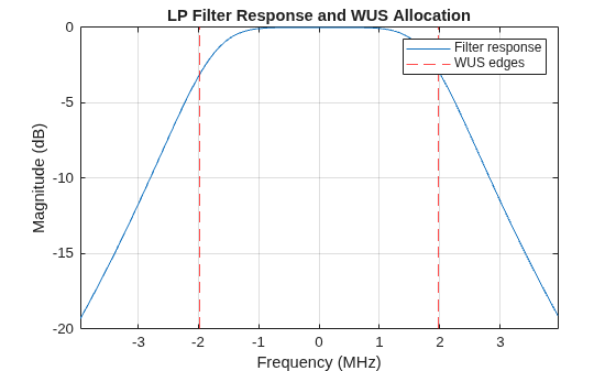
Third order Butterworth LP filter matching the WUS bandwidth
This example focuses on physical-layer detection performance and does not model higher-layer procedures such as DRX cycle timing, paging occasion (PO) to LP-WUS occasion (LO) association, as defined in TS 38.213 Section 10.4C, paging frame selection, or RRC configuration signaling from SIB1.
Configure Carrier and LP-WUS Parameters
Configure a 20 MHz carrier with 51 RBs at 30 kHz subcarrier spacing. Set the LP-WUS to occupy 11 PRBs starting at RB 3 with OOK symbols per OFDM symbol and a duration of 10 OFDM symbols. Using provides a good balance between OOK symbol energy and the number of available coded bits. A single ZC root sequence (root index 25) generates the ON-sequences. Setting NumSequences to 4 enables sequence-based modulation, which the CD receiver uses for improved detection performance.
The wake-up information payload encodes the paging occasion index or subgroup index depending on the RRC configuration, as defined in TS 38.213 Section 10.4C and TS 38.331 by the higher layer parameter lowPower-Config-r19. This example uses random information bits to evaluate detection performance independently of higher-layer content.
% Create an empty parameters structure
simParameters = struct;

% Simulation sweep parameters
simParameters.SNRdB = [-9 -7 -5 -3];
simParameters.NumTrials = 200;
simParameters.NumBits = 5;

% ED receiver options
simParameters.EnableFilter = true;
simParameters.FilterOrder = 3;

% Carrier configuration
simParameters.Carrier = nrCarrierConfig;
simParameters.Carrier.SubcarrierSpacing = 30; % 15, 30 kHz
simParameters.Carrier.NSizeGrid = 51;

% LP-WUS configuration
simParameters.LPWUS = hLPWUSConfig;
simParameters.LPWUS.NumOOKSymbolsPerOFDM = 2;  % M = 1, 2, 4
simParameters.LPWUS.NumOFDMSymbols = 10;       % M=1: 2..64, M=2: 1..32, M=4: 1..16
simParameters.LPWUS.RootSequence = 25;         % 1..NZC-1
simParameters.LPWUS.NumSequences = 4;          % 1, 2, 4, 8, 16 (max depends on M)
simParameters.LPWUS.StartRB = 3;
simParameters.LPWUS.StartSymbol = 3;
Configure Channel Model
Configure a TDL-C channel with 300 ns delay spread and 5 Hz maximum Doppler shift.
channel = nrTDLChannel;
channel.DelayProfile = "TDL-C";
channel.DelaySpread = 300e-9;
channel.MaximumDopplerShift = 5;
channel.NumTransmitAntennas = 1;
channel.NumReceiveAntennas = 1;

carrier = simParameters.Carrier;
ofdmInfo = nrOFDMInfo(carrier);
channel.SampleRate = ofdmInfo.SampleRate;
Design ED Receiver Filter
The ED receiver uses a third-order Butterworth low-pass filter to isolate the WUS band before energy detection. The filter bandwidth matches the LP-WUS allocation of 132 subcarriers at 30 kHz spacing, which accounts for 3.96 MHz. Compute the frequency offset to mix the received signal to baseband, centering on the WUS allocation before filtering.
lpwus = simParameters.LPWUS;
scsHz = carrier.SubcarrierSpacing * 1e3;
gridStartSc = -carrier.NSizeGrid * 12 / 2;
lpwusCenterSc = gridStartSc + lpwus.StartRB * 12 + lpwus.NumSubcarriers / 2;
fcCenter = lpwusCenterSc * scsHz;
lpwusBW = lpwus.NumSubcarriers * scsHz;
[bFilt, aFilt] = butter(simParameters.FilterOrder, (lpwusBW/2) / (ofdmInfo.SampleRate/2));
Verify that the filter passband aligns with the WUS frequency allocation.
plotFilterResponse(bFilt, aFilt, carrier.SubcarrierSpacing, ofdmInfo.SampleRate);
Run Detection Simulation
For each SNR point, transmit random LP-WUS codepoints through the fading channel, apply AWGN, and decode with the ED and CD receivers. The ED segments the received waveform into OOK symbol intervals, computes the energy in each interval, then applies Manchester decoding to produce soft bits for channel decoding. The CD performs OFDM demodulation, extracts the LP-WUS subcarriers, and correlates against reference ZC sequences for joint ML detection. The MDR is the fraction of trials where the decoded bits do not match the transmitted bits.
numBits = simParameters.NumBits;
nTrials = simParameters.NumTrials;
SNRdB = simParameters.SNRdB;
enableFilter = simParameters.EnableFilter;
symPerSlot = carrier.SymbolsPerSlot;
numLPWUSSlots = ceil((lpwus.StartSymbol + lpwus.NumOFDMSymbols) / symPerSlot);
missRateED = zeros(size(SNRdB));
missRateCD = zeros(size(SNRdB));
pathFilters = getPathFilters(channel);
chInfo = info(channel);
ind = hLPWUSIndices(carrier, lpwus);

for snrIdx = 1:numel(SNRdB)

    rng("default");
    reset(channel);

    numPassED = 0;
    numPassCD = 0;

    for trial = 0:nTrials-1

        % Generate random information bits and encode
        bits = randi([0 1], numBits, 1);
        [g, f1] = hLPWUSEncode(bits, lpwus.E, lpwus.NumSequences);
        sym = hLPWUS(lpwus, g, f1);

        % Build transmit grid and place WUS symbols
        txGrid = repmat(nrResourceGrid(carrier), 1, numLPWUSSlots);
        txGrid(ind) = sym;
        [txWaveform, ofdmInfo] = nrOFDMModulate(carrier, txGrid, Windowing=0);

        % Pass through fading channel
        txWaveform = [txWaveform; zeros(chInfo.MaximumChannelDelay, chInfo.NumTransmitAntennas)];
        [rxWaveform, pathGains] = channel(txWaveform);

        % Add AWGN at the target SNR
        snr = 10^(SNRdB(snrIdx)/10);
        N0 = 1/sqrt(ofdmInfo.Nfft * channel.NumReceiveAntennas * snr);
        noise = N0 * randn(size(rxWaveform), "like", rxWaveform);
        rxWaveform = rxWaveform + noise;

        % Perfect timing synchronization
        timingOffset = nrPerfectTimingEstimate(pathGains, pathFilters);
        rxWaveform = rxWaveform(timingOffset+1:end,:);

        % Mix to baseband and apply LP filter
        if enableFilter
            t = (0:size(rxWaveform, 1)-1).' / ofdmInfo.SampleRate;
            rxWaveform = rxWaveform .* exp(-1j*2*pi*fcCenter*t);
            rxWaveform = filter(bFilt, aFilt, rxWaveform);
            rxWaveform = rxWaveform .* exp(+1j*2*pi*fcCenter*t);
        end

        % Energy detection
        softBits = hLPWUSDecodeED(carrier, lpwus, rxWaveform);

        % LLR soft decoding is identical to small block length nrUCIDecode
        % using 1 bit per symbol
        decbitsED = nrUCIDecode(softBits, numBits, "pi/2-BPSK");

        % Score detection outcome for ED
        numPassED = numPassED + isequal(decbitsED, bits);

        % OFDM demodulation and coherent detection
        rxGridCD = nrOFDMDemodulate(carrier, rxWaveform);
        rxSym = nrExtractResources(ind, rxGridCD);
        decbitsCD = hLPWUSDecodeCD(carrier, lpwus, rxSym, numBits);

        % Score detection outcome for CD
        numPassCD = numPassCD + isequal(decbitsCD, bits);
    end

    missRateED(snrIdx) = 1 - numPassED/nTrials;
    missRateCD(snrIdx) = 1 - numPassCD/nTrials;

    % Display results at this SNR point
    disp("SNR = " + sprintf("%+.1f", SNRdB(snrIdx)) + " dB: " ...
        + numPassED + "/" + nTrials + " passed, MDR (ED): " ...
        + sprintf("%.2f", missRateED(snrIdx)) ...
        + " | " + numPassCD + "/" + nTrials + " passed, MDR (CD): " ...
        + sprintf("%.2f", missRateCD(snrIdx)))

end
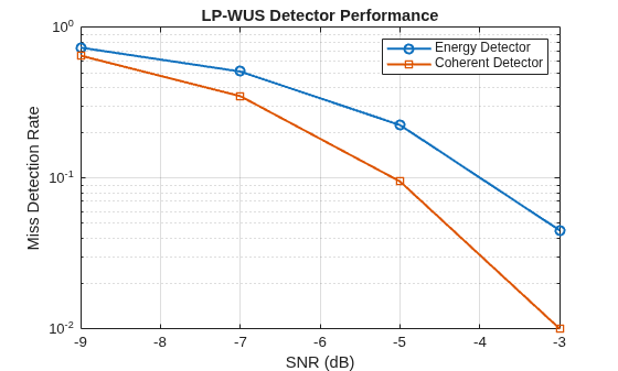
SNR = -9.0 dB: 53/200 passed, MDR (ED): 0.73 | 70/200 passed, MDR (CD): 0.65
SNR = -7.0 dB: 98/200 passed, MDR (ED): 0.51 | 130/200 passed, MDR (CD): 0.35
SNR = -5.0 dB: 155/200 passed, MDR (ED): 0.22 | 181/200 passed, MDR (CD): 0.09
SNR = -3.0 dB: 191/200 passed, MDR (ED): 0.05 | 198/200 passed, MDR (CD): 0.01
Analyze Results
Plot the MDR as a function of SNR. The conformance target is 1% MDR at the required SNR operating point, as defined in TS 38.101-4 Section 5.7. The CD receiver achieves this target at a lower SNR than the ED receiver under TDL-C 300 ns conditions.
semilogy(SNRdB, missRateED, "-o", SNRdB, missRateCD, "-s", LineWidth=1.5)
legend("Energy Detector", "Coherent Detector")
xlabel("SNR (dB)")
ylabel("Miss Detection Rate")
title("LP-WUS Detector Performance")
grid on
Further Exploration
To extend this example, consider the following variations:
Vary the order of the ED filter to evaluate the detection performance of higher or lower quality filters.
Vary
NumOOKSymbolsPerOFDMto evaluate the trade-off between OOK symbol duration and the number of coded bits available for detection.Replace perfect timing synchronization with LP-SS-based synchronization to evaluate the impact of timing errors on detection performance.
Add multiple receive antennas and evaluate noncoherent combining gain.
References
[1] S. Wagner, "Low-Power Wake-Up Signal Design in 3GPP 5G-Advanced Release 19," arXiv:2507.10207v2, Feb. 2026.
[2] 3GPP TS 38.211 "NR; Physical channels and modulation." 3rd Generation Partnership Project; Technical Specification Group Radio Access Network.
[3] 3GPP TS 38.212, "NR; Multiplexing and channel coding." 3rd Generation Partnership Project; Technical Specification Group Radio Access Network.
[4] 3GPP TS 38.213, "NR; Physical layer procedures." 3rd Generation Partnership Project; Technical Specification Group Radio Access Network.
[5] 3GPP TS 38.101-4, "NR; User Equipment (UE) radio transmission and reception; Part 4." 3rd Generation Partnership Project; Technical Specification Group Radio Access Network.
Local Functions
function plotFilterResponse(b, a, scs, sampleRate)

    [hFilt, fFilt] = freqz(b, a, 2048, sampleRate, "whole");
    hFilt = fftshift(hFilt);
    fFilt = fFilt - fFilt(end/2);
    plot(fFilt/1e6, 20*log10(abs(hFilt)))
    hold on
    nsc = hLPWUSConfig.NumSubcarriers;
    xline((-nsc/2) * scs / 1e3, "r--")
    xline((nsc/2) * scs / 1e3, "r--")
    hold off
    xlabel("Frequency (MHz)")
    ylabel("Magnitude (dB)")
    title("LP Filter Response and WUS Allocation")
    legend("Filter response", "WUS edges")
    grid on
    xlim(nsc/2 * scs / 1e3 * [-2 2])

end

