NR PUSCH Throughput with Transport Block over Multiple Slots
R2026bThis example shows how to measure the physical uplink shared channel (PUSCH) throughput of a 5G New Radio (NR) link with transport block processing over multiple slots (TBoMS). You can perform perfect or practical synchronization and channel estimation. To reduce the total simulation time, you can execute the signal-to-noise ratio (SNR) points in the SNR loop in parallel by using the Parallel Computing Toolbox™ software.
Introduction
This example measures the PUSCH throughput of a 5G link using TBoMS, as defined in 3GPP TS 38.211, TS 38.212, TS 38.213, and TS 38.214.
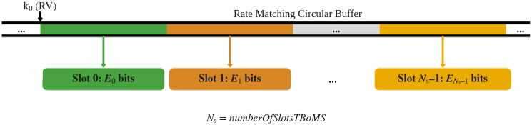
3GPP Release 17 introduced TBoMS as part of the NR coverage enhancements work item (TS 38.212, TS 38.214). A single transport block (TB) is transmitted across multiple slots. The number of slots is configured by the numberOfSlotsTBoMS RRC parameter, as defined in TS 38.331. The TB is encoded into a single LDPC code block. This figure shows the uplink shared channel (UL-SCH) rate matching with TBoMS. Each slot starts reading the LDPC buffer at the point where the previous slot finished reading. HARQ operates on the TB across multiple slots as a single entity.
The example models these 5G NR features:
UL-SCH transport channel processing with TBoMS
PUSCH type-A repetition
PUSCH and PUSCH DM-RS generation
Variable subcarrier spacing and frame numerologies ( kHz)
Normal and extended cyclic prefix
TDL and CDL propagation channel models
Other features of the simulation are:
Optional PUSCH transform precoding
Slot-wise and non-slot-wise PUSCH and DM-RS mapping
Perfect or practical synchronization and channel estimation
HARQ operation
To reduce the total simulation time, you can use the Parallel Computing Toolbox software to execute the SNR points of the SNR loop in parallel.
Simulation Length and SNR Points
Set the length of the simulation in terms of the number of 10 ms frames. To produce meaningful throughput results, update NFrames to a large number. Set the SNR points to simulate. The example defines SNR per RE and applies the SNR to each receive antenna. For an explanation of the SNR definition that this example uses, see SNR Definition Used in Link Simulations.
simParameters = struct(); % Create a structure to contain all key simulation parameters simParameters.NFrames =2; % Number of 10 ms frames simParameters.SNRIn =
[-5 0 5]; % SNR range (dB)
Channel Estimator Configuration
Use the PerfectChannelEstimator variable to control channel estimation and synchronization behavior. When set to true, the example uses perfect channel estimation and synchronization. Otherwise, the example uses practical channel estimation and synchronization based on the values of the received PUSCH DM-RS.
simParameters.PerfectChannelEstimator =  true;
true;Simulation Diagnostics
Use the DisplaySimulationInformation variable to control the display of simulation information such as the HARQ process ID used for each slot. In case of a CRC error, the example also displays the value of the index to the RV sequence.
simParameters.DisplaySimulationInformation =  true;
true;Carrier Configuration
Set the carrier resource grid parameters. This example uses the parameters from TS 38.104 Table 8.2.12-1 as the default.
simParameters.Carrier = nrCarrierConfig; % Carrier resource grid configuration simParameters.Carrier.NSizeGrid =5; % Bandwidth in number of resource blocks (5 RBs at 15 kHz SCS) simParameters.Carrier.SubcarrierSpacing =
15; % Subcarrier spacing (kHz) simParameters.Carrier.CyclicPrefix = 'Normal'; % 'Normal' or 'Extended' (Extended CP is relevant for 60 kHz SCS only) simParameters.Carrier.NCellID = 0; % Cell identity
PUSCH Configuration
Set the PUSCH parameters including resource allocation, modulation, and DM-RS. This example assumes fixed PUSCH configuration across all simulated slots.
simParameters.PUSCH = nrPUSCHConfig;
Set the PUSCH time-frequency resource allocation per slot to a single full grid BWP.
simParameters.PUSCH.PRBSet =  0:simParameters.Carrier.NSizeGrid-1;
simParameters.PUSCH.SymbolAllocation = [0,simParameters.Carrier.SymbolsPerSlot];
Set the mapping type, scrambling identifiers, transform precoding, and modulation scheme.
simParameters.PUSCH.MappingType = 'A';   % 'A'(slot-wise), 'B'(non-slot-wise)
simParameters.PUSCH.NID = simParameters.Carrier.NCellID;
simParameters.PUSCH.RNTI = 1;
simParameters.PUSCH.TransformPrecoding = false;
simParameters.PUSCH.Modulation = 'QPSK'; % 'pi/2-BPSK', 'QPSK', '16QAM', '64QAM', '256QAM'
Configure the PUSCH DM-RS.
simParameters.PUSCH.DMRS.DMRSTypeAPosition = 2;       % Mapping type A only. First DM-RS symbol position (2, 3)
simParameters.PUSCH.DMRS.DMRSLength = 1;              % Number of front-loaded DM-RS symbols (1(single symbol), 2(double symbol))
simParameters.PUSCH.DMRS.DMRSAdditionalPosition = 1;  % Additional DM-RS symbol positions (max range 0...3)
simParameters.PUSCH.DMRS.DMRSConfigurationType = 1;   % DM-RS configuration type (1, 2)
simParameters.PUSCH.DMRS.NumCDMGroupsWithoutData = 2; % Number of CDM groups without data
simParameters.PUSCH.DMRS.NIDNSCID = 0;                % Scrambling identity (0...65535)
simParameters.PUSCH.DMRS.NSCID = 0;                   % Scrambling initialization (0, 1)
simParameters.PUSCH.DMRS.NRSID = 0;                   % Scrambling ID for low-PAPR sequences (0...1007)
simParameters.PUSCH.DMRS.GroupHopping = 0;            % Group hopping (0, 1)
simParameters.PUSCH.DMRS.SequenceHopping = 0;         % Sequence hopping (0, 1)
simParameters.PUSCH.DMRS.DMRSPortSet = [];            % Use this to specify explicit DM-RS port numbers (TS 38.212 Section 7.3.1.1). Empty corresponds to the first NumLayers valid ports
UL-SCH Configuration
Set the UL-SCH transport channel processing parameters including the TBoMS and HARQ parameters.
simParameters.PUSCHExtension = struct(); simParameters.PUSCHExtension.NumberOfSlotsTBoMS =4; % Number of slots for transport block processing simParameters.PUSCHExtension.NumRepetitionTypeA =
4; % Number of Type-A repetitions simParameters.PUSCHExtension.RVSequence = [0 2 3 1]; % RV sequence for repetition simParameters.PUSCHExtension.TargetCodeRate =
193 / 1024; % Target code rate of the whole block simParameters.PUSCHExtension.XOverhead = 0; % Rate matching overhead for TBS (Xoh)
Set HARQ parameters.
simParameters.PUSCHExtension.NHARQProcesses = 16; % Number of parallel HARQ processes to use
simParameters.PUSCHExtension.EnableHARQ = true;   % Enable retransmissions for each process, using RV sequence [0 2 3 1]
Antenna Geometry and Propagation Channel
Set the number of receive antennas. This example supports single-input multiple-output (SIMO) configurations where a signal from a single transmit antenna is received by one or more receive antennas.
simParameters.NRxAnts = 2; % Number of receive antennasConfigure a CDL or TDL propagation channel model. Set DelayProfile to 'None' to disable channel impairments. For CDL channels, the example converts the number of antenna elements into an antenna panel configuration.
simParameters.DelayProfile        = 'TDL-B'; % 'TDL-A', ..., 'TDL-E', 'CDL-A', ..., 'CDL-E', 'None'
simParameters.DelaySpread         = 100e-9;
simParameters.MaximumDopplerShift = 400;

% Cross-check parameters before simulation
validateNumLayers(simParameters);

waveformInfo = nrOFDMInfo(simParameters.Carrier);
[channel,simParameters] = createChannel(simParameters,waveformInfo);

% Get the maximum channel delay
chInfo     = info(channel);
maxChDelay = chInfo.MaximumChannelDelay;
Processing Loop
To determine the throughput at each SNR point, the example analyzes PUSCH data on a per-slot basis. Each TBoMS bundle, consisting of a given number of slots (NumberOfSlotsTBoMS), shares a single transport block and HARQ entity. Physical channel processing is independent per slot:
Update current HARQ process: Determine whether a new transport block or a retransmission is required in the first slot of every TBoMS bundle.
UL-SCH encoding: On the first slot of the bundle, encode and rate-match the transport block across all slots in the bundle. The first slot starts at the RV-indicated circular buffer position; subsequent slots continue from where the previous slot left off.
Generate grid and waveform: Modulate the coded bits onto PUSCH resource elements and OFDM-modulate the resource grid.
Model noisy channel: Pass the waveform through a CDL or TDL fading channel and add AWGN.
Perform synchronization and OFDM demodulation: For perfect synchronization, reconstruct the channel impulse response to synchronize the received waveform. For practical synchronization, correlate the received waveform with the PUSCH DM-RS. Then OFDM demodulate the synchronized signal.
Perform channel estimation and equalization: For perfect channel estimation, reconstruct the channel impulse response and perform OFDM demodulation. For practical channel estimation, use the PUSCH DM-RS. MMSE equalize the channel by using the
nrEqualizeMMSEfunction.Decode the PUSCH: Demodulate and descramble the recovered PUSCH symbols along with a noise estimate by using the
nrPUSCHDecodefunction.UL-SCH decoding: Rate-recover and accumulate soft bits into the N-domain soft buffer every slot. The decoder attempts LDPC decoding only when it receives all slots in the bundle.
To reduce the total simulation time, you can execute the processing loop in parallel by using the Parallel Computing Toolbox software. For parallel processing, comment out the for statement and uncomment the parfor statement. If Parallel Computing Toolbox is not installed, parfor defaults to the traditional for statement. Because parfor-loop iterations are executed in parallel in a nondeterministic order, the simulation information displayed for each SNR point can be intertwined. To switch off simulation information display, set the DisplaySimulationInformation variable to false.
% Array to store the maximum throughput for all SNR points
maxThroughput = zeros(length(simParameters.SNRIn),1);
% Array to store the simulation throughput for all SNR points
simThroughput = zeros(length(simParameters.SNRIn),1);

% Define RV at first occurrence and use RV only here
if simParameters.PUSCHExtension.EnableHARQ
    rvSeq  = simParameters.PUSCHExtension.RVSequence;
    % Expand RV sequence to match its length to the number of Type-A repetitions
    numRVs = numel(rvSeq);
    numRep = simParameters.PUSCHExtension.NumRepetitionTypeA;
    rvSeq = rvSeq(mod((0:numRep-1),numRVs)+1);
else
    % HARQ disabled - single transmission with RV=0, no retransmissions
    rvSeq = 0;
end

% Calculate the number of RBs in one slot, transport block size, and
% aggregated bit capacity of the multiple slots. Also calculate PUSCH
% indices in each slot as PUSCH configuration is fixed in all slots.
[puschIndices,puschIndicesInfo] = nrPUSCHIndices(simParameters.Carrier,simParameters.PUSCH);
MRB = numel(puschIndicesInfo.PRBSet);
trBlkSize = nrTBS(simParameters.PUSCH.Modulation,simParameters.PUSCH.NumLayers, ...
    MRB*simParameters.PUSCHExtension.NumberOfSlotsTBoMS,puschIndicesInfo.NREPerPRB, ...
    simParameters.PUSCHExtension.TargetCodeRate,simParameters.PUSCHExtension.XOverhead);
GBundle = simParameters.PUSCHExtension.NumberOfSlotsTBoMS*puschIndicesInfo.G;

for snrIdx = 1:numel(simParameters.SNRIn)    % comment out for parallel computing
% parfor snrIdx = 1:numel(simParameters.SNRIn) % uncomment for parallel computing

    % Reset the random number generator so that each SNR point will
    % experience the same noise realization
    rng('default');

    % Take full copies of the simulation-level parameter structures so that they are not
    % PCT broadcast variables when using parfor
    simLocal = simParameters;
    waveinfoLocal = waveformInfo;

    % Take copies of channel-level parameters to simplify subsequent parameter referencing
    carrier = simLocal.Carrier;
    pusch = simLocal.PUSCH;
    puschextra = simLocal.PUSCHExtension;

    % Prepare simulation for new SNR point
    SNRdB = simLocal.SNRIn(snrIdx);
    fprintf('\nSimulating (1x%d) SCS=%dkHz with %s channel at %gdB SNR for %d 10ms frame(s)\n', ...
        simLocal.NRxAnts,carrier.SubcarrierSpacing,simLocal.DelayProfile,SNRdB,simLocal.NFrames);

    % Specify the fixed order for the HARQ process IDs to cycle through
    harqSequence = 0:puschextra.NHARQProcesses-1;

    % Initialize the state of all HARQ processes
    harqEntity = HARQEntity(harqSequence,rvSeq,pusch.NumCodewords);

    % Reset the channel so that each SNR point will experience the same
    % channel realization
    reset(channel);

    % Total number of slots in the simulation period
    NSlots = simLocal.NFrames * carrier.SlotsPerFrame;

    % Timing offset, updated in every slot for perfect synchronization and
    % when the correlation is strong for practical synchronization
    offset = 0;

    % Noise power, normalized by the IFFT size used in OFDM modulation, as
    % the OFDM modulator applies this normalization to the transmitted
    % waveform. Also normalize by the number of receive antennas, as the
    % channel model applies this normalization to the received waveform
    % by default
    SNR = 10^(SNRdB/10);
    N0 = 1/sqrt(simLocal.NRxAnts*waveinfoLocal.Nfft*SNR);
    nVar = N0^2*waveinfoLocal.Nfft;

    % Initialize the array to store the decoder states and transport blocks
    % for each HARQ process
    initCell      = repmat({[]},puschextra.NHARQProcesses,1);
    nSlotInBundle = 0;        % TBoMS slot number counter inside the bundle
    dstate        = initCell; % Decoder states
    trBlk         = initCell; % Transport block

    % Loop over the entire waveform length
    for nslot = 0:NSlots-1

        % Update the carrier slot numbers for new slot
        carrier.NSlot = nslot;

        % At the first slot of each TBoMS slot bundle, create a new UL-SCH
        % transport block if this is the initial transmission of the
        % current HARQ process. Encode once and rate-match across all slots
        % in the bundle.
        if nSlotInBundle == 0
            if harqEntity.NewData
                % New transmission: reset decoder state completely
                dstate{harqEntity.HARQProcessID+1} = [];
                % Create new UL-SCH transport block
                trBlk{harqEntity.HARQProcessID+1} = randi([0 1],trBlkSize,1);
            else
                % Retransmission: keep soft buffer for combining, clear
                % buffered LLRs from previous bundle attempt
                dstate{harqEntity.HARQProcessID+1}.SlotLLRs = [];
            end

            % UL-SCH encoding: perform LDPC encoding on the whole transport
            % block and per-slot rate matching. Store the encoded bits for
            % each slot in a matrix
            codedSlots = hULSCHEncode( ...
                trBlk{harqEntity.HARQProcessID+1},pusch.Modulation, ...
                puschIndicesInfo.G,puschextra.TargetCodeRate, ...
                harqEntity.RedundancyVersion,puschextra.NumberOfSlotsTBoMS);
        end

        % Select coded bits for current slot in the bundle
        codedTrBlock = codedSlots(:,nSlotInBundle+1);

        % Create resource grid for a slot
        puschGrid = nrResourceGrid(carrier);

        % PUSCH modulation and mapping to resource grid
        puschSymbols = nrPUSCH(carrier,pusch,codedTrBlock);
        puschGrid(puschIndices) = puschSymbols;

        % Generate PUSCH DM-RS symbols and map to resource grid
        dmrsSymbols = nrPUSCHDMRS(carrier,pusch);
        dmrsIndices = nrPUSCHDMRSIndices(carrier,pusch);
        puschGrid(dmrsIndices) = dmrsSymbols;

        % OFDM modulation
        txWaveform = nrOFDMModulate(carrier,puschGrid);

        % Pass data through channel model. Append zeros at the end of the
        % transmitted waveform to flush channel content. These zeros take
        % into account any delay introduced in the channel. This is a mix
        % of multipath delay and implementation delay. This value may
        % change depending on the sampling rate, delay profile, and delay
        % spread. The channel model also returns the OFDM channel response
        % and timing offset for the specified carrier
        txWaveform = [txWaveform; zeros(maxChDelay,size(txWaveform,2))]; %#ok<AGROW>
        [rxWaveform,ofdmResponse,timingOffset] = channel(txWaveform,carrier);

        % Add AWGN to the received time-domain waveform
        noise = N0*randn(size(rxWaveform),"like",rxWaveform);
        rxWaveform = rxWaveform + noise;

        if (simLocal.PerfectChannelEstimator)
            % For perfect synchronization, use the timing offset obtained
            % from the channel
            offset = timingOffset;
        else
            % Practical synchronization. Correlate the received waveform
            % with the PUSCH DM-RS to give timing offset estimate 't' and
            % correlation magnitude 'mag'. The function
            % hSkipWeakTimingOffset is used to update the receiver timing
            % offset. If the correlation peak in 'mag' is weak, the current
            % timing estimate 't' is ignored and the previous estimate
            % 'offset' is used
            [t,mag] = nrTimingEstimate(carrier,rxWaveform,dmrsIndices,dmrsSymbols);
            offset = hSkipWeakTimingOffset(offset,t,mag);
            % Display a warning if the estimated timing offset exceeds the
            % maximum channel delay
            if offset > maxChDelay
                warning(['Estimated timing offset (%d) is greater than the maximum channel delay (%d).' ...
                    ' This will result in a decoding failure. This may be caused by low SNR,' ...
                    ' or not enough DM-RS symbols to synchronize successfully.'],offset,maxChDelay);
            end
        end
        rxWaveform = rxWaveform(1+offset:end,:);

        % Perform OFDM demodulation on the received data to recreate the
        % resource grid, including padding, when practical synchronization
        % results in an incomplete slot being demodulated
        rxGrid = nrOFDMDemodulate(carrier,rxWaveform);
        [K,L,R] = size(rxGrid);
        if (L < carrier.SymbolsPerSlot)
            rxGrid = cat(2,rxGrid,zeros(K,carrier.SymbolsPerSlot-L,R));
        end

        if (simLocal.PerfectChannelEstimator)
            % For perfect channel estimate, use the OFDM channel response
            % obtained from the channel
            estChannelGrid = ofdmResponse;

            % Use the precalculated noise variance as the perfect noise
            % estimate
            noiseEst = nVar;
        else
            % Practical channel estimation using the PUSCH DM-RS
            dmrsLayerSymbols = nrPUSCHDMRS(carrier,pusch);
            dmrsLayerIndices = nrPUSCHDMRSIndices(carrier,pusch);
            [estChannelGrid,noiseEst] = nrChannelEstimate(carrier,rxGrid,dmrsLayerIndices,dmrsLayerSymbols,'CDMLengths',pusch.DMRS.CDMLengths);
        end

        % Get PUSCH resource elements from the received grid
        [puschRx,puschHest] = nrExtractResources(puschIndices,rxGrid,estChannelGrid);

        % Equalization
        [puschEq,csi] = nrEqualizeMMSE(puschRx,puschHest,noiseEst);

        % Decode PUSCH physical channel
        [ulschLLRs,rxSymbols] = nrPUSCHDecode(carrier,pusch,puschEq,noiseEst);

        % Apply channel state information (CSI) produced by the equalizer,
        % including the effect of transform precoding if enabled
        if (pusch.TransformPrecoding)
            MSC = MRB * 12;
            csi = nrTransformDeprecode(csi,MRB) / sqrt(MSC);
            csi = repmat(csi((1:MSC:end).'),1,MSC).';
            csi = reshape(csi,size(rxSymbols));
        end
        Qm = length(ulschLLRs) / length(rxSymbols);
        csi = reshape(repmat(csi.',Qm,1),[],1);
        ulschLLRs = ulschLLRs .* csi;

        % UL-SCH decoding. Rate recover and accumulate soft bits every slot.
        % LDPC decoding is only attempted once all TBoMS slots in a bundle
        % have been received.
        lastSlotInBundle = (nSlotInBundle == puschextra.NumberOfSlotsTBoMS-1);
        [decbits,blkerr,dstate{harqEntity.HARQProcessID+1}] = hULSCHDecode(ulschLLRs,pusch.Modulation, ...
            harqEntity.RedundancyVersion,trBlkSize,puschextra.TargetCodeRate, ...
            dstate{harqEntity.HARQProcessID+1},lastSlotInBundle);

        % Update HARQ process with transport block CRC error at the last
        % slot in each bundle
        if lastSlotInBundle
            % Store values to calculate throughput
            simThroughput(snrIdx) = simThroughput(snrIdx) + (~blkerr * trBlkSize);
            maxThroughput(snrIdx) = maxThroughput(snrIdx) + trBlkSize;

            % Update current process with CRC error and advance to next process
            procstatus = updateAndAdvance(harqEntity,blkerr,trBlkSize,GBundle);
            if (simLocal.DisplaySimulationInformation)
                firstSlot = nslot-puschextra.NumberOfSlotsTBoMS+1;
                fprintf('\n(%3.2f%%) NSlot=%d:%d, %s', ...
                    100*(nslot+1)/NSlots,firstSlot,nslot,procstatus);
            end
        end

        % Advance TBoMS slot counter
        nSlotInBundle = mod(nSlotInBundle+1,puschextra.NumberOfSlotsTBoMS);

    end

    % Display the results dynamically in the command window
    if (simLocal.DisplaySimulationInformation)
        fprintf('\n');
    end
    fprintf('\nThroughput (Mbps) for %d frame(s) = %.4f\n',simLocal.NFrames,1e-6*simThroughput(snrIdx)/(simLocal.NFrames*10e-3));
    fprintf('Throughput (%%) for %d frame(s) = %.4f\n',simLocal.NFrames,simThroughput(snrIdx)*100/maxThroughput(snrIdx));

end
Simulating (1x2) SCS=15kHz with TDL-B channel at -5dB SNR for 2 10ms frame(s)
(20.00%) NSlot=0:3, HARQ Proc 0: CW0: Initial transmission passed  (TBS=1128,RV=0,CR=0.195833).
(40.00%) NSlot=4:7, HARQ Proc 1: CW0: Initial transmission passed  (TBS=1128,RV=0,CR=0.195833).
(60.00%) NSlot=8:11, HARQ Proc 2: CW0: Initial transmission failed  (TBS=1128,RV=0,CR=0.195833).
(80.00%) NSlot=12:15, HARQ Proc 3: CW0: Initial transmission failed  (TBS=1128,RV=0,CR=0.195833).
(100.00%) NSlot=16:19, HARQ Proc 4: CW0: Initial transmission failed  (TBS=1128,RV=0,CR=0.195833).
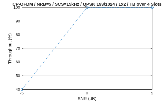
Throughput (Mbps) for 2 frame(s) = 0.1128
Throughput (%) for 2 frame(s) = 40.0000
Simulating (1x2) SCS=15kHz with TDL-B channel at 0dB SNR for 2 10ms frame(s)
(20.00%) NSlot=0:3, HARQ Proc 0: CW0: Initial transmission passed  (TBS=1128,RV=0,CR=0.195833).
(40.00%) NSlot=4:7, HARQ Proc 1: CW0: Initial transmission passed  (TBS=1128,RV=0,CR=0.195833).
(60.00%) NSlot=8:11, HARQ Proc 2: CW0: Initial transmission passed  (TBS=1128,RV=0,CR=0.195833).
(80.00%) NSlot=12:15, HARQ Proc 3: CW0: Initial transmission passed  (TBS=1128,RV=0,CR=0.195833).
(100.00%) NSlot=16:19, HARQ Proc 4: CW0: Initial transmission passed  (TBS=1128,RV=0,CR=0.195833).
Throughput (Mbps) for 2 frame(s) = 0.2820
Throughput (%) for 2 frame(s) = 100.0000
Simulating (1x2) SCS=15kHz with TDL-B channel at 5dB SNR for 2 10ms frame(s)
(20.00%) NSlot=0:3, HARQ Proc 0: CW0: Initial transmission passed  (TBS=1128,RV=0,CR=0.195833).
(40.00%) NSlot=4:7, HARQ Proc 1: CW0: Initial transmission passed  (TBS=1128,RV=0,CR=0.195833).
(60.00%) NSlot=8:11, HARQ Proc 2: CW0: Initial transmission passed  (TBS=1128,RV=0,CR=0.195833).
(80.00%) NSlot=12:15, HARQ Proc 3: CW0: Initial transmission passed  (TBS=1128,RV=0,CR=0.195833).
(100.00%) NSlot=16:19, HARQ Proc 4: CW0: Initial transmission passed  (TBS=1128,RV=0,CR=0.195833).
Throughput (Mbps) for 2 frame(s) = 0.2820
Throughput (%) for 2 frame(s) = 100.0000
Results
Display the measured throughput. The example calculates the throughput as the percentage of the maximum possible throughput of the link given the available resources for data transmission.
plotResults(simParameters,simThroughput,maxThroughput);
% Bundle key parameters and results into a combined structure for recording
simResults.simParameters = simParameters;
simResults.simThroughput = simThroughput;
simResults.maxThroughput = maxThroughput;
References
[1] 3GPP TS 38.211. "NR; Physical channels and modulation." 3rd Generation Partnership Project; Technical Specification Group Radio Access Network.
[2] 3GPP TS 38.212. "NR; Multiplexing and channel coding." 3rd Generation Partnership Project; Technical Specification Group Radio Access Network.
[3] 3GPP TS 38.213. "NR; Physical layer procedures for control." 3rd Generation Partnership Project; Technical Specification Group Radio Access Network.
[4] 3GPP TS 38.214. "NR; Physical layer procedures for data." 3rd Generation Partnership Project; Technical Specification Group Radio Access Network.
[5] 3GPP TS 38.331. "NR; Radio Resource Control (RRC); Protocol specification." 3rd Generation Partnership Project; Technical Specification Group Radio Access Network.
[6] 3GPP TS 38.104. "NR; Base Station (BS) radio transmission and reception." 3rd Generation Partnership Project; Technical Specification Group Radio Access Network.
Local Functions
function validateNumLayers(simParameters)
% Validate the number of layers relative to the antenna geometry

    validateattributes(simParameters.PUSCHExtension.NumberOfSlotsTBoMS, ...
        {'numeric'},{'integer','positive'},'','NumberOfSlotsTBoMS');
    numlayers = simParameters.PUSCH.NumLayers;
    if numlayers ~= 1
        error('The number of layers (%d) must be 1. This example only supports single-layer PUSCH.', ...
            numlayers);
    end

end

function [channel,simParameters] = createChannel(simParameters,waveformInfo)
% Construct the CDL or TDL channel model object

    if contains(simParameters.DelayProfile,'CDL','IgnoreCase',true)
        channel = nrCDLChannel; % CDL channel object

        % Swap transmit and receive sides as the default CDL channel is
        % configured for downlink transmissions.
        swapTransmitAndReceive(channel);

        % Turn the number of antennas into antenna panel array layouts. If
        % NRxAnts is not one of (1,2,4,8,16,32,64,128,256,512,1024), its value
        % is rounded up to the nearest value in the set.
        channel = hArrayGeometry(channel,1,simParameters.NRxAnts,'uplink');
        simParameters.NRxAnts = prod(channel.ReceiveAntennaArray.Size);
    else
        channel = nrTDLChannel; % TDL channel object

        % Configure the channel to automatically select a sample rate for
        % generating channel coefficients
        channel.PathGainSampleRate = 'auto';

        % Swap transmit and receive sides as the default TDL channel is
        % configured for downlink transmissions
        swapTransmitAndReceive(channel);

        % Set the channel geometry
        channel.NumTransmitAntennas = 1;
        channel.NumReceiveAntennas = simParameters.NRxAnts;
    end

    % Assign simulation channel parameters and waveform sample rate to the
    % object, and specify OFDM channel response as the channel response output
    % so that perfect channel estimate is calculated while filtering the signal
    channel.DelayProfile = simParameters.DelayProfile;
    if ~strcmp(channel.DelayProfile,"None")
        channel.DelaySpread = simParameters.DelaySpread;
        channel.MaximumDopplerShift = simParameters.MaximumDopplerShift;
        channel.SampleRate = waveformInfo.SampleRate;
    end
    channel.ChannelResponseOutput = 'ofdm-response';
end

function plotResults(simParameters,simThroughput,maxThroughput)
% Plot the simulation results

    figure;
    plot(simParameters.SNRIn,simThroughput*100./maxThroughput,'o-.')
    xlabel('SNR (dB)'); ylabel('Throughput (%)'); grid on;
    if (simParameters.PUSCH.TransformPrecoding)
        ofdmType = 'DFT-s-OFDM';
    else
        ofdmType = 'CP-OFDM';
    end
    title(sprintf('%s / NRB=%d / SCS=%dkHz / %s %d/1024 / 1x%d / TB over %d Slots', ...
        ofdmType,simParameters.Carrier.NSizeGrid,simParameters.Carrier.SubcarrierSpacing, ...
        simParameters.PUSCH.Modulation, ...
        round(simParameters.PUSCHExtension.TargetCodeRate*1024), ...
        simParameters.NRxAnts, ...
        simParameters.PUSCHExtension.NumberOfSlotsTBoMS));
end
See Also
nrULSCH | nrULSCHDecoder | nrTDLChannel | nrCDLChannel | nrPUSCHDecode | nrPUSCH | parfor
See Also
Topics
- NR NTN PDSCH Throughput
- NR PUSCH Throughput
- Model NR NTN Channel (Satellite Communications Toolbox)

