Model, Analyze and Compare Horn Antennas
This example shows how to model, analyze the pattern and compare the gains of different types of horn antennas. Horn antennas are essentially a section of a waveguide where the open end is flared to provide a transition to the areas of free space. This antenna is a simple development of a waveguide transmission line. It is possible to leave a waveguide open and let signal radiate, but this is not efficient. Signals passing along the waveguide see a sudden transition from the waveguide to free space, which cause the signals to be reflected back along the waveguide as standing waves. To overcome this issue the waveguide can be tapered out or flared, for providing a gradual transition from the impedance of the waveguide to that of free space.
Rectangular Horns
This type of horn antennas has a rectangular shaped waveguide, typically fed by a monopole. In such horns, flaring is done in both E-plane & H-plane walls of the rectangular waveguide. Aperture of the horn is rectangular. The parameters listed below will be used in modeling this type of horn.
FL = Flare Length of the horn
FW = Flare Width of the horn
FH = Flare Height of the horn
L = Length of the waveguide
W = Width of the waveguide
H = Height of the waveguide
For example:
FL = 0.0348;
FW = 0.035;
FH = 0.035;
L = 0.03;
W = 0.024;
H = 0.012;
FO = [0.01 0];
ant1 = horn(FlareLength=FL, FlareWidth=FW, FlareHeight=FH, Length=L,...
    Width=W, Height=H, FeedOffset=FO);
show(ant1)
Conical Horn
This conical horn has a circular shaped waveguide. Aperture of this antenna is circular rather than rectangular with a cone shaped structure coming out of the waveguide. The parameters listed below will be used in modeling this type of horn.
R = Radius of the circular waveguide
WH = Height of the circular waveguide
CH = Height of the cone
AR = ApertureRadius of the cone
For example:
R = 0.012;
WH = 0.03;
CH = 0.0348;
AR = 0.035;
ant2 = hornConical(Radius=R, WaveguideHeight=WH, ConeHeight=CH,...
    ApertureRadius=AR);
show(ant2)
Conical Corrugated Horn
The corrugated horn antenna is like an extension for the conical horn with some additional features. This antenna consists of slots or grooves covering the inner surface of the cone. Typically, such type of horns has 5 to 6 corrugations per wavelength.

z1 = FirstCorrugateDistance, Distance from end of the waveguide to the first corrugate. Corrugations on the surface of the cone start with a metal followed by a groove and repeats itself along the length of the cone. So, the distance is measured from the end of the waveguide to the end of the first groove.
p = Pitch, Distance between two successive corrugations. Number of corrugations can be controlled with this property
w = CorrugateWidth, Width of the groove or corrugation.
d1=CorrugateDepth, Depth of the corrugation. Typically, depth is selected such that it is equal to 0.25
For example:
z1 = 0.006;
p = 0.0036;
w = 0.0014;
d1 = 0.004;
ar = 0.018;
ch = 0.0348;
ant3 = hornConicalCorrugated(FirstCorrugateDistance=z1, Pitch=p,...
CorrugateWidth=w, CorrugateDepth=d1, ConeHeight=ch, ApertureRadius=ar);
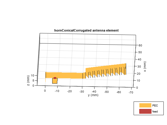
show(ant3)
Cross sectional view of the corrugated horn:
xlim([0 60]);
zlim([0 10]);
view(-88,35);
Rectangular Corrugated Horn
Rectangular corrugated horn is an extension for horn antenna with corrugations along the width and height of the flare.
FL = Flare Length of the horn
FW = Flare Width of the horn
FH = Flare Height of the horn
L = Length of the waveguide
W = Width of the waveguide
H = Height of the waveguide
FCD = First Corrugate Distance
CD = CorrugateDepth
For example:
FL = 0.0348;
FW = 0.035;
FH = 0.035;
L = 0.03;
W = 0.024;
H = 0.012;
FCD = 0.01;
CD = [0.005 0.0075];
ant4 = hornCorrugated(FlareLength=FL, FlareWidth=FW, FlareHeight=FH, Length=L,...
              Width=W, Height=H, FirstCorrugateDistance=FCD, CorrugateDepth=CD);
show(ant4)
Applications
Horn antennas are widely used in satellite communications as feed antennas in cassegrain, parabolic reflector antennas. These antennas direct the beam towards the reflector. Let us compare the gain provided by these antennas in such applications.
For the cassegrain antenna with the horn as the exciter, analyze the pattern at 10 GHz. Create a PatternPlotOptions object to re-scale the magnitude for the plot.
ant5 = cassegrain;
ant5.Exciter = ant1;
ant5.Exciter.Tilt = 270;
ant5.Exciter.TiltAxis = [0 1 0];
az = 0:2:360;
el = -90:1:90;
patOpt = PatternPlotOptions;
patOpt.MagnitudeScale = [-15 35];
pattern(ant5,10e9,az,el,PatternOptions=patOpt);

For the cassegrain antenna with the hornConical as the exciter,analyze the pattern at 10 GHz
ant5.Exciter = ant2;
ant5.Exciter.Tilt = -90;
figure
pattern(ant5,10e9,az,el,PatternOptions=patOpt);

For the cassegrain antenna with the hornConicalCorrugated as the exciter, analyze the pattern at 10 GHz. The gain provided by the corrugated horn antenna is more compared to other horns due to corrugate depth and pitch of the corrugations which result in lower side lobes.
ant5.Exciter = ant3;
ant5.Exciter.Tilt = -90;
figure
[~] = mesh(ant5,MaxEdgeLength=0.01);
pattern(ant5,10e9,az,el,PatternOptions=patOpt);

For the cassegrain antenna with the hornCorrugated as the exciter, plot the radiation pattern at 10 GHz.
ant5.Exciter = ant4;
ant5.Exciter.Tilt = 270;
ant5.Exciter.TiltAxis = [0 1 0];
figure
pattern(ant5,10e9,az,el,PatternOptions=patOpt);

Conclusion
Horn antennas often have a directional radiation pattern with a higher antenna gain and are relatively easy to manufacture.
References
[1] P. Piksa, "Comparison of conical horn with optimized corrugated surface and corrugated horn," Proceedings of 21st International Conference Radioelektronika 2011, Brno, 2011, pp. 1-3.
[2] R. P. Jadhav, V. Javnrakash Dongre and A. Heddallikar, "Design of X-Band Conical Horn Antenna Using Coaxial Feed and Improved Design Technique for Bandwidth Enhancement," 2017 International Conference on Computing, Communication, Control and Automation (ICCUBEA), Pune, 2017, pp. 1-6.