Architectural Data Editor
Description
The Architectural Data Editor lets you edit the Architectural Data section of a Simulink® data dictionary. By using the Architectural Data Editor, you can manage interfaces, data types, and constants that are used by Simulink and shared across architectural models.
With the Architectural Data Editor you can:
Create and configure definitions for interfaces, data types, and constants.
Filter, sort, and search architectural data in the main Contents pane. See Filter and Manage Entries in Contents Pane for more information.
Manage the architectural data of multiple data dictionaries.
Configure platform agnostic architectural data properties by selecting the Architectural Data option in the View tab of the editor toolstrip.
Configure AUTOSAR Classic platform properties of architectural data by selecting the Architectural Data > AUTOSAR Classic option in the View tab of the editor toolstrip. When the editor is in the AUTOSAR Classic view, you can add data and edit properties that are specific to the AUTOSAR Classic Platform. For example, you can:
Configure AUTOSAR XML options and share them across models.
Export architectural data and AUTOSAR definitions to ARXML and other supporting files.
Import and manage profiles and stereotypes using the Architectural Data Editor. Access the Profile Editor (System Composer) from the Architectural Data Editor from the Profiles tab and select the
 Profile Editor button.
Manage and save requirement links using Requirements Toolbox™
 and track changes using a traceability matrix. For more
information, see Track Requirement Links with a Traceability Matrix (Requirements Toolbox).
and track changes using a traceability matrix. For more
information, see Track Requirement Links with a Traceability Matrix (Requirements Toolbox).
For more information about shared interfaces and data types, see Store Shared Data in Architectural Data Section and Store Data in Architectural Data Section Programmatically, and Manage Interfaces with Data Dictionaries (System Composer).
Open the Architectural Data Editor
You can open the Architectural Data Editor using any of the following methods:
Open Model Explorer by double-clicking an
.slddfile, then navigate to the Architectural Data section and click the Open Architectural Data Editor button.From the Interface Editor (System Composer) of a system architecture model, click the Manage interfaces, data types and dictionary references in Architectural Data Editor
 button.
From the Interface Editor of an AUTOSAR architecture model, click the Open Dictionary
 button.
From the Modeling tab of a system architecture model, select Design > Architectural Data Editor.
Use the
showfunction on an Architectural Data object.arDataObj = Simulink.dictionary.archdata.create("newDictionary.sldd"); show(arDataObj)At the MATLAB® command prompt, enter
archdataeditor.
Examples
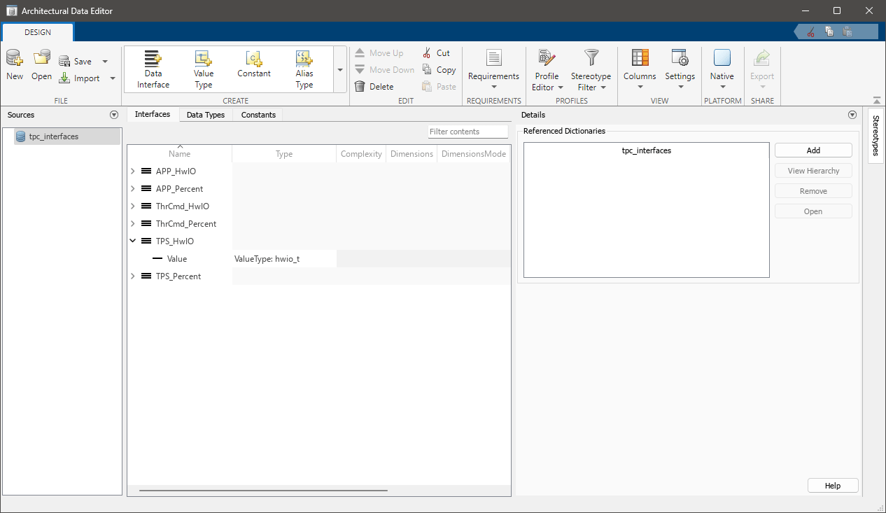
You can create a data dictionary from the Architectural Data Editor and then edit the architectural data.
From the Architectural Data Editor, to create a new data dictionary, from the File section, click New.
To configure architectural data for an existing data dictionary, click Open and select the data dictionary. Add interfaces, data types, and constants by navigating to the Create tab and selecting the desired data object.
You can move design data to the Architectural Data section by opening a data
dictionary in Model Explorer and right clicking the design data element, from the
context menu select Treat as Architectural Data. You can move data
from the Architectural Data section to Design Data by right-clicking the data element in
the Architectural Data Editor and selecting Move to Design
Data. You can also use the moveToDesignData function.
Note
You may need to use the convertToStructType function when moving structs from Design Data to
the Architectural Data section.
You can create a data dictionary and return the Architectural Data object programmatically.
Use the Simulink.dictionary.archdata.create function to create an Architectural
Data object and an associated data
dictionary.
archDataObj = Simulink.dictionary.archdata.create('newDictionary.sldd');To begin editing architectural data in an existing data dictionary use the Simulink.dictionary.archdata.open function.
archDataObj = Simulink.dictionary.archdata.open('dataDictionary.sldd');Add interfaces, data types, and constants by using the Simulink.dictionary.ArchitecturalData programmatic interfaces. For more
information see Store Data in Architectural Data Section Programmatically.
You can open multiple data dictionaries in a single editor window and switch between them by using the Sources pane.
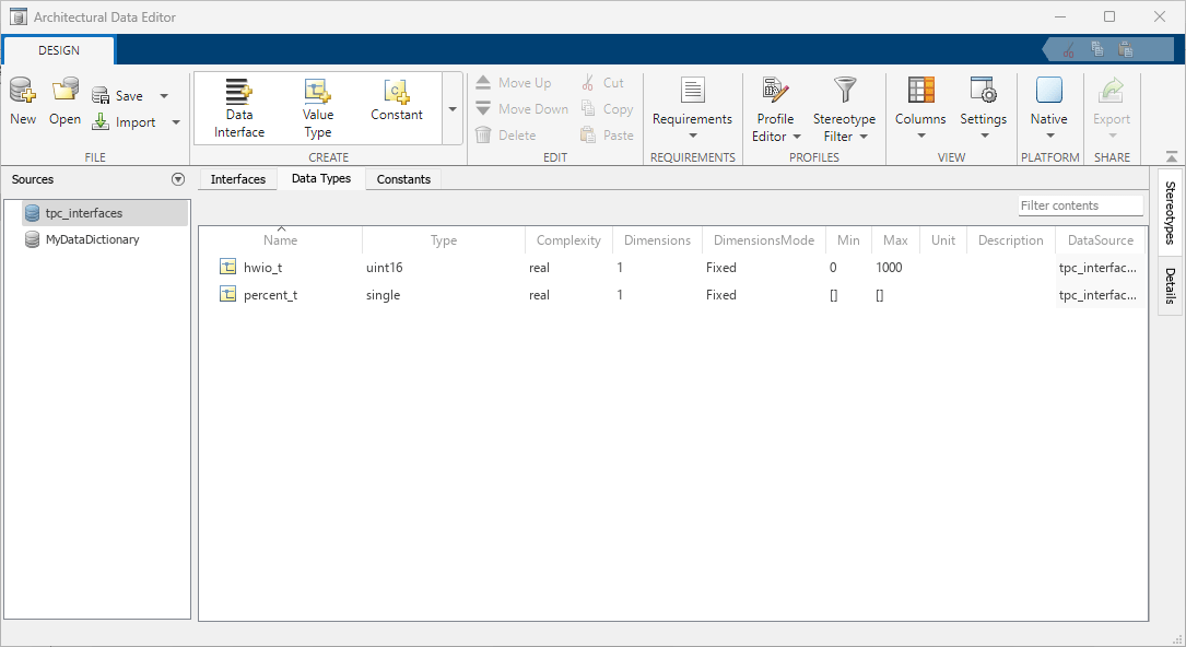
To manage architectural data of multiple data dictionaries:
From the File section, click Open to open existing data dictionaries or click New to create new data dictionaries.
From the Sources pane, select a data dictionary.
Select the Interfaces, Data Types, Constants, or platform-specific tabs to view and edit architectural data. See Create and Configure Interface, Data Type, and Constant Definitions for more information.
On the Interfaces and Data Types tabs, the Architectural Data Editor provides a DataSource column indicating the source data dictionary for each interface or data type.
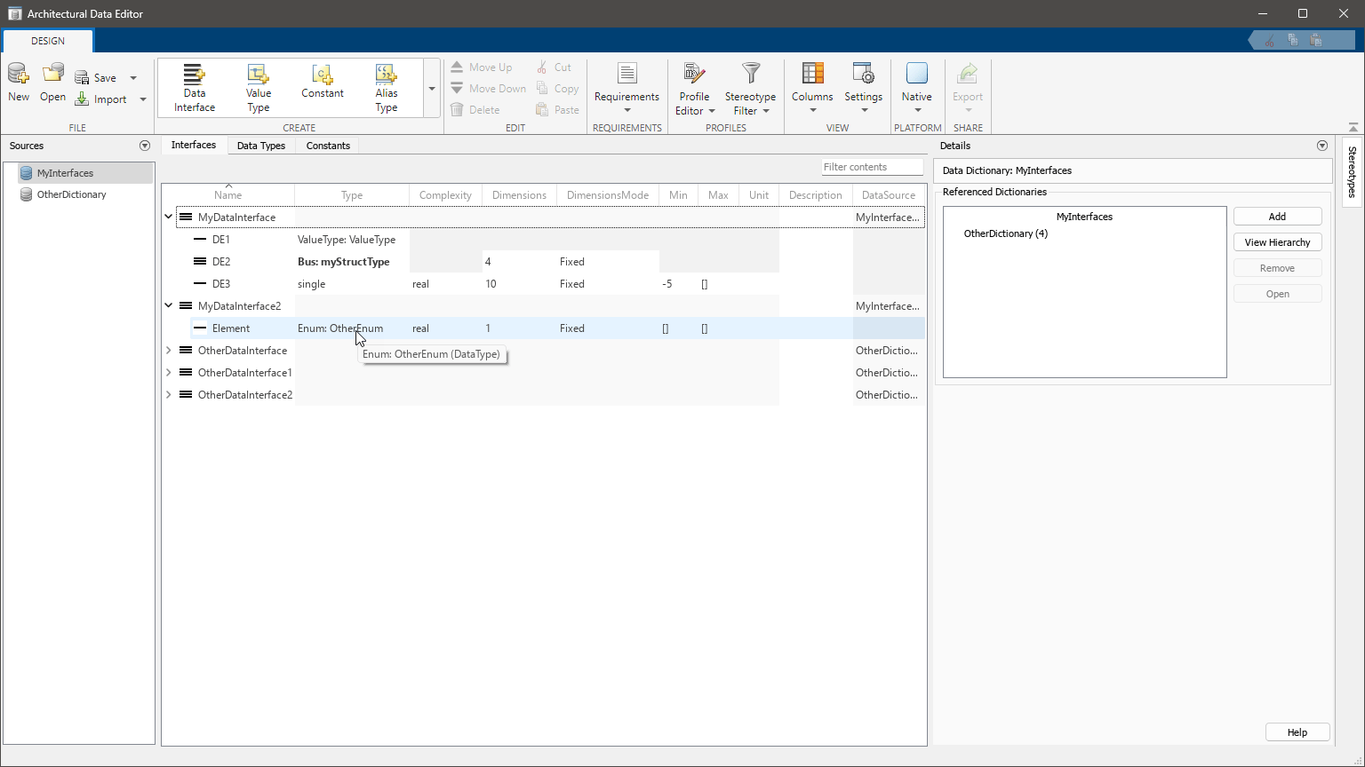
To reference a data dictionary from another data dictionary:
Open both data dictionaries.
From the Sources pane, double-click the name of the data dictionary to which you want to add a referenced data dictionary. The Details pane displays the Referenced Dictionaries section.
In the Details pane, click Add to add a referenced dictionary. The main Contents pane displays the architectural data in the referenced data dictionary.
On the toolstrip, under Settings, select or clear Include content from referenced dictionaries to show or hide the data from referenced data dictionaries.
Once a data dictionary is referenced, architectural data from the
referenced dictionary can be used by the open dictionary that references it. For
example, the image shows that the data element in data interface
MyDataInterface2 uses enumeration OtherEnum from
the referenced dictionary OtherDictionary for its data type.
From the Referenced Dictionaries section of the Details pane, you can add references to existing data dictionaries, remove references, or open referenced data dictionaries in the Sources pane.
Note
You cannot reference data dictionaries from Simulink data dictionaries that are mapped to the AUTOSAR Classic Platform. For more information see Configure AUTOSAR Classic Platform Properties in Architectural Data Section (AUTOSAR Blockset).
You can create interfaces, data types, and constants to be shared among both architecture models and other Simulink models and configure their associated properties.
On the toolstrip, in the Create section, add interface, data type, and constant definitions on the Interfaces, Data Types, and Constants tabs, respectively, by clicking the data type, interface, and constant icons.
To configure interfaces, data types, and constants, on the Interfaces, Data Types, Constants tabs, select an interface, data type, or constant object and edit its properties in the main Contents pane and in the Details pane.
On the Interfaces tab, you can view service interfaces
previously created in System Composer or by using the getInterface and getInterfaceNames functions.
You can also add interfaces, data types, and constants programmatically. Add data
types by using the addAliasType, addEnumType, addNumericType, addStructType, and addValueType functions.
| Supported Data Types | Architectural Data Editor Operations |
|---|---|
| Alias Type | Add a |
| Enumerated Type | Add a Simulink enumeration data type |
| Numeric Type | Add a |
| Structured Type | Add a |
| Value Type | Add a |
Add interfaces using the addDataInterface, addServiceInterface, addPhysicalInterface functions.
Add elements to interfaces using the programmatic interfaces of the Simulink.dictionary.archdata.DataInterface object and configure those
elements using the Simulink.dictionary.archdata.DataElement object.
| Supported Interfaces and Elements | Architectural Data Editor Operations |
|---|---|
| Data Interface | Add a data interface object to the Architectural Data section. For
information about performing this operation programmatically, see |
| Data Element | Add a data element object to the selected data interface. For information
about performing this operation programmatically, see addElement. |
| Physical Interface | Add a physical interface object to the Architectural Data section. For
information about performing this operation programmatically, see addPhysicalInterface. |
| Physical Element | Add a physical element object to the selected physical interface. For
more information about performing this operation programmatically, see
addElement. |
| Service Interface | Add a service interface object to the Architectural Data section. For
information about performing this operation programmatically, see addServiceInterface. |
| Service Element | Add a service element object to the selected service interface. For more
information about performing this operation programmatically, see addElement. |
| Function Element | Function elements are Simulink.dictionary.archdata.FunctionElement objects and are
derived from the prototype of their service element |
Note
Physical interfaces are not supported for the AUTOSAR Classic platform. For the AUTOSAR Adaptive platform you can configure service interfaces using a data dictionary with no applied platform mapping.
Add a Simulink.dictionary.archdata.Constant object to the dictionary by using the
addConstant function.
When you save the Architectural Data section, the properties that you configured are
stored in the .sldd file.
The main Contents pane provides an interactive table with information about the interface, data types, and constants objects, such as hierarchy and properties. You can select which columns appear in the table by selecting Columns in the toolstrip.
Use the main Contents pane to:
Filter objects — Enter a universal filter or a column-specific filter.
Edit objects — Double-click a value in the table and enter a new value. When you enter a value that is not supported, a diagnostic message appears in the pane.
Batch edit objects — Select objects of the same type that you want to edit. Double-click a value of one of the selected objects and enter a new value. The new value applies to all selected objects.
Reorder interface and structure type element objects — Drag an element object to a new position, or select an element object and click the Move Up and Move Down buttons in the toolstrip.
Copy, cut, and paste objects — Select an object and press keyboard shortcuts or click the corresponding buttons in the toolstrip.
Delete objects — Select an element object and press the Delete key or click the Delete button in the toolstrip. When you delete an interface object, you also delete the interface element objects it contains.
For more information about using the Contents pane, see Manage Interfaces with Data Dictionaries (System Composer).
Version History
Introduced in R2023bCut and paste architectural data entries across permitted tabs and data dictionaries.
Select the architectural data entry and click the Cut icon ![]() located in the Edit section of the
Architectural Data Editor toolstrip. You can also right-click the
architectural data entry and select the Cut option from the context
menu, or use the keyboard shortcut Ctrl + X.
located in the Edit section of the
Architectural Data Editor toolstrip. You can also right-click the
architectural data entry and select the Cut option from the context
menu, or use the keyboard shortcut Ctrl + X.
See Also
Objects
Simulink.dictionary.ArchitecturalData|Simulink.dictionary.archdata.AliasType|Simulink.dictionary.archdata.Constant|Simulink.dictionary.archdata.DataInterface|Simulink.dictionary.archdata.DataElement|Simulink.dictionary.archdata.EnumType|Simulink.dictionary.archdata.Enumeral|Simulink.dictionary.archdata.FunctionElement|Simulink.dictionary.archdata.FunctionArgument|Simulink.dictionary.archdata.NumericType|Simulink.dictionary.archdata.PhysicalInterface|Simulink.dictionary.archdata.ServiceInterface|Simulink.dictionary.archdata.StructElement|Simulink.dictionary.archdata.ValueType|Simulink.dictionary.archdata.StructType