Author AUTOSAR Adaptive Compositions with Software Architectures
R2026bThis example shows how to develop AUTOSAR software compositions and components for the AUTOSAR Adaptive Platform by using a software architecture model.
An AUTOSAR architecture model provides resources and a canvas for developing AUTOSAR composition and component models. From the architecture model, you can:
Add and connect AUTOSAR compositions and components.
Create architecture views for analysis.
Link components to requirements (requires Requirements Toolbox).
Define algorithm implementations for software components by creating, importing, or linking Simulink models.
Define and share port interfaces, data types, and constants by using Simulink data dictionaries.
Configure and simulate software component communication and execution behavior in a mock ARA environment.
Model and simulate asynchronous, synchronous, and fire-and-forget method communication.
Design Service Interfaces for each software component in an AUTOSAR Adaptive software composition independent of the software component model algorithm.
Configure deployment properties including middleware configurations for DDS or SOME/IP.
Export composition and component ARXML descriptions.
Build and generate component algorithm and service code and applications by using a single-build action (requires Embedded Coder).
Verify generated C++ code by using software-in-the-loop (SIL) simulations.
Deploy AUTOSAR software components as applications from an AUTOSAR composition to a POSIX-based execution environment (requires Embedded Coder Support Package for Service-Oriented Applications on Linux).
Create AUTOSAR Adaptive Software Architecture Model
Create a software architecture model configured for the AUTOSAR Adaptive Platform. In this example you create a version of example model adaptive_BrakeControlSystem, this completed model is available for your reference.
arch = autosar.arch.createModel("my_adaptive_BrakeControlSystem",platform="Adaptive");
Add and Connect AUTOSAR Adaptive Components and Compositions
After you create an AUTOSAR software architecture model, you use the composition editor and the Simulink Toolstrip Modeling tab to add and connect AUTOSAR compositions and components.
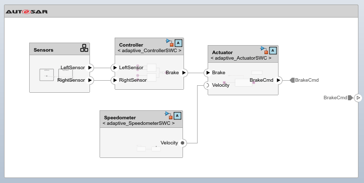
Add a Sensors Software Composition block to the architecture model. Within the composition, add two Adaptive Component blocks named LeftData and RightData to represent individual sensor software components.
sensors = addComposition(arch,"Sensors");
leftSensorSWC = addComponent(sensors,"LeftData",Kind="AdaptiveApplication");
rightSensorSWC = addComponent(sensors,"RightData",Kind="AdaptiveApplication");
leftPort = addPort(leftSensorSWC,"Sender","Sensor");
rightPort = addPort(rightSensorSWC,"Sender","Sensor");
Add Adaptive Component blocks at the top level of the architecture for the actuator, controller, and speedometer.
actuator = addComponent(arch,"Actuator",Kind="AdaptiveApplication");
controller = addComponent(arch,"Controller",Kind="AdaptiveApplication");
speedometer = addComponent(arch,"Speedometer",Kind="AdaptiveApplication");
Add sender ports to the Sensors composition so that internal sensor components can communicate with other top-level components. Add a BrakeCmd sender port to the boundary of the software architecture. Signal lines between software component models and data ports exiting or entering the parent composition represent AUTOSAR delegation connectors. Add signal lines representing AUTOSAR delegation connectors inside the Sensors Software Composition block by using the connect function.
ports = addPort(sensors,"Sender",{'LeftSensor','RightSensor'});
addPort(arch,"Sender","BrakeCmd");
connect(sensors,leftPort,ports(1));
connect(sensors,rightPort,ports(2));
Add behavior to each Adaptive Component block by using the linkToModel function to link each block to an existing software component model. The software component models used in this architecture have already been created for this example. The Sensors Software Composition block uses multi-instantiation by reusing the software component model adaptive_SensorSWC to handle inputs from multiple sensors.
linkToModel(leftSensorSWC,"adaptive_SensorSWC");
linkToModel(rightSensorSWC,"adaptive_SensorSWC");
linkToModel(actuator,"adaptive_ActuatorSWC");
Setting 'XML Options Source' of model 'adaptive_ActuatorSWC' to 'Inherit' so that it inherits XML option settings from architecture model. Resave the model to preserve the setting change.
linkToModel(controller,"adaptive_ControllerSWC");
linkToModel(speedometer,"adaptive_SpeedometerSWC");
Signal lines between component models represent AUTOSAR assembly connectors. Add signal lines representing AUTOSAR assembly connectors between software components by using the connect function.
connect(arch,sensors,controller);
connect(arch,controller,actuator);
connect(arch,speedometer,actuator);
connect(arch,actuator,[]);
layout(arch)
Configure Port Interfaces of AUTOSAR Adaptive Components, Compositions, and Architectures
Port interfaces define the data elements and service methods that components use to communicate. In this example, the port interfaces are defined in the brakeControlPortInterfaces.sldd data dictionary.
Link the data dictionary to the architecture model so that port interfaces resolve at the architecture level.
linkDictionary(arch,"brakeControlPortInterfaces.sldd");Inspect the available interfaces on the architecture model by opening the Architectural Data section of the dictionary.
archdata = Simulink.dictionary.archdata.open("brakeControlPortInterfaces.sldd");The data dictionary contains three port interfaces:
BrakeInterface— ASimulink.dictionary.archdata.DataInterfacewith elementsBrakeCmdandCmdfor brake command signals. Components use bus element ports to send and receive individual data elements from this interface.SensorInterface— ASimulink.dictionary.archdata.DataInterfacewith aDistanceelement for sensor measurements. TheControllercomponent receives sensor data through bus element inports, includingDistance_statuselements that monitor communication health using theSlSignalStatusenumeration.SpeedInterface— ASimulink.dictionary.archdata.ServiceInterfacewith agetCurrentVelocityfunction element for client-server communication. TheSpeedometercomponent exposes a server function port that implements this method. TheActuatorcomponent calls it as a client using a Function Caller block, receiving both avelocityvalue and anSlSignalStatusreturn argument.
In the software component models, bus element ports provide access to individual data elements within a Simulink.dictionary.archdata.DataInterface. For example, the Controller model uses an In Bus Element block mapped to data interface elements LeftSensor.Distance and RightSensor.Distance. Function ports implement client-server communication defined by a Simulink.dictionary.archdata.ServiceInterface object. The Speedometer model algorithm implements a server method by using a function-call triggered subsystem getCurrentVelocity. The Actuator software component model contains a Function Caller block that models the client that invokes the Speedometer server.
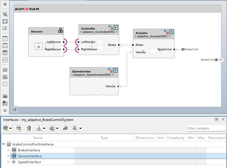
When you link component models by using the linkToModel function, the architecture automatically resolves port interfaces for those components from the linked dictionary. However, software composition ports do not automatically inherit these port interfaces. Assign the SensorInterface to the Sensors composition outports by using the setInterface function.
sensorIf = getInterface(archdata,"SensorInterface");
setInterface(leftSensorSWC.Ports(1),sensorIf);
setInterface(rightSensorSWC.Ports(1),sensorIf);
setInterface(sensors.Ports(1),sensorIf);
setInterface(sensors.Ports(2),sensorIf);
You can configure C++ namespaces of each port interface when they are stored in the Architectural Data section of a linked data dictionary. When you generate code, the software generates Proxy/Skeleton headers in a directory structure compliant with the AUTOSAR Adaptive standard.
brakeIf = getInterface(archdata,"BrakeInterface");
sensorIf = getInterface(archdata,"SensorInterface");
speedIf = getInterface(archdata,"SpeedInterface");

brakeIf.CppNamespace = "company::chassis::braking";
sensorIf.CppNamespace = "company::chassis::perception";
speedIf.CppNamespace = "company::chassis::dynamics";
Simulate AUTOSAR Adaptive Software Composition Behavior
When you simulate an AUTOSAR Adaptive software architecture model, the software executes all referenced component algorithms together to simulate software composition behavior. The service interface specifications of each software component become service contracts that are enforced by the execution environment during simulation. In software architectures, simulation of AUTOSAR Adaptive software compositions includes:
Data-triggered execution — Functions configured with On data arrival, execute are triggered by the simulation when data is delivered to the corresponding port. This models the AUTOSAR Adaptive runtime where application runnables execute in response to received service events.
Client-server communication — The simulation invokes server methods on behalf of client components and returns both the response value and a communication status argument.
Communication status reporting — Software component models use the built-in data type
SlSignalStatusstatus elements (sender-receiver) and status arguments (client-server) to design your intent for detecting and handling component communication errors. During simulation with fully connected architectures, status arguments and elements have valueSlSignalStatus.OK.
Open the Controller software component implementation model and inspect the status elements used in the model algorithm. The Controller component receives sensor data through bus element ports LeftSensor.Distance and RightSensor.Distance. Each Distance data element has a corresponding Distance_status bus element port with data type Enum: SlSignalStatus.
open_system("adaptive_ControllerSWC")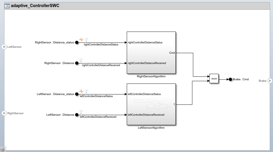
Simulate Data-Triggered Execution of AUTOSAR Adaptive Software Component
The Actuator component demonstrates data-triggered execution behavior during simulation. Open the Actuator implementation model to inspect how it uses a function-call trigger to execute its algorithm only when new data is delivered to its Brake receiver port.
open_system("adaptive_ActuatorSWC");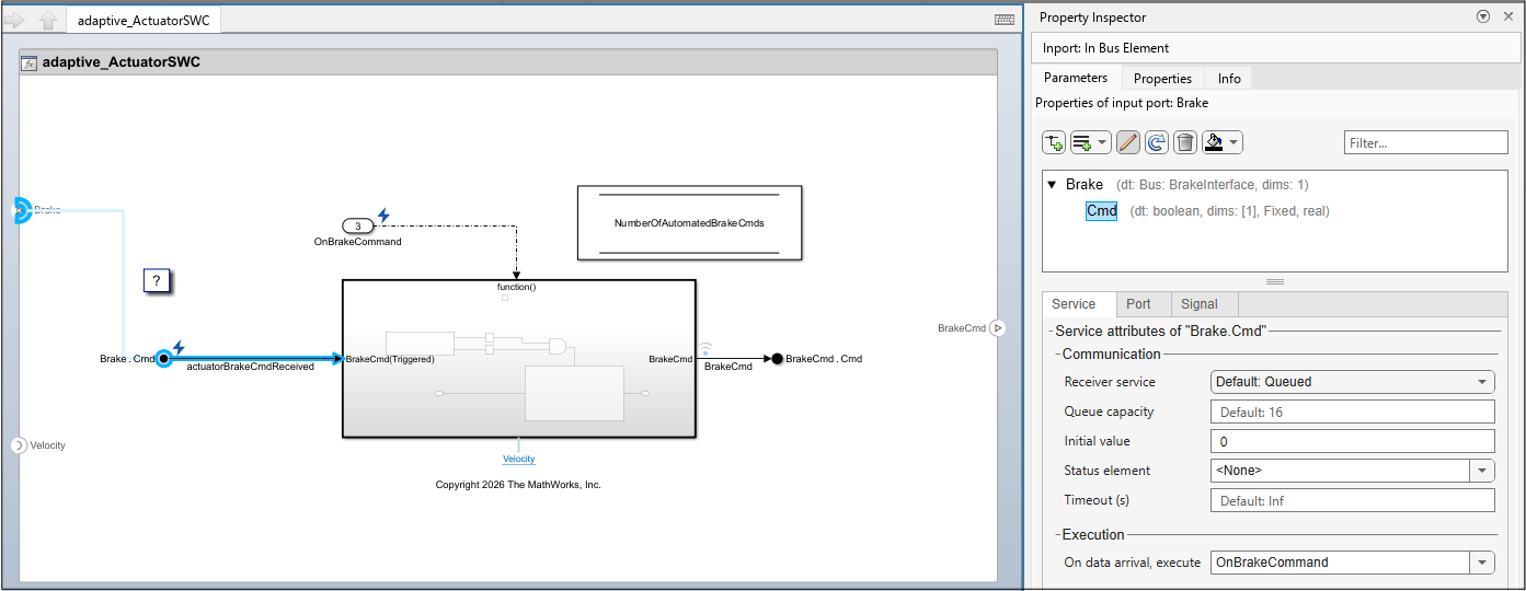
The Actuator model contains a Function-Call Subsystem triggered by the OnBrakeCommand inport. This inport is configured with On data arrival, execute behavior, meaning the simulation triggers the Actuator algorithm each time the Controller publishes a new brake command. The Actuator component also calls the Speedometer server method getCurrentVelocity() which returns both a velocity value and a status argument. This models design intent for the execution environment run-time behavior where applications execute in response to received events.
Inside the triggered subsystem, the Actuator algorithm uses the arguments returned by Speedometer server method getCurrentVelocity() and the incoming BrakeCmd to determine when to send a brake command to the system. The enabled subsystem only sends a brake command when the arguments returned by getCurrentVelocity() are a positive value for velocity and the signal status is SlSignalStatus.OK.
Simulate the architecture and observe the Actuator output. The BrakeCmd output reflects the data-triggered execution. The Actuator produces output only at time steps when it receives new data from the Controller, and non-negative velocity from the Speedometer.
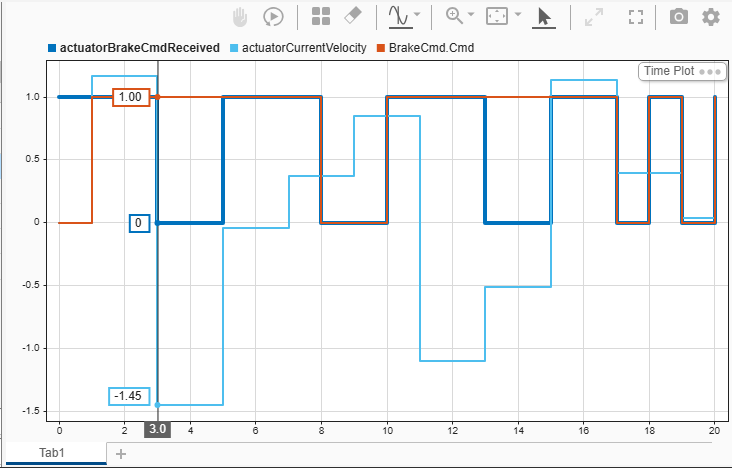
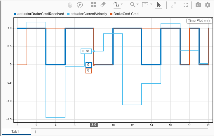
simOut = sim("my_adaptive_BrakeControlSystem");Open the Simulation Data Inspector, the output shows that the Actuator executes only when new valid data arrives on the Brake.Cmd port, and when the received velocity is positive with the status argument reporting SlSignalStatus.OK.
At t=3.0s the data received on port Brake.Cmd changes to a value of 0. However, the velocity is negative, so the output of the system does not change. Since the client port is configured to allow for asynchronous execution (Caller behavior is set to Allow for delayed server results) the Actuator is not blocked from execution and sends output that is calculated with the last valid values that it received from other components in the architecture.
At t=8.0s, port Brake.Cmd receives new data, triggering the function-call subsystem to execute. Since the current velocity is positive, the logic in the function-call subsystem changes the output of the system.
Communication Error Status Configuration
During simulation, all connected ports report SlSignalStatus.OK because the simulation environment provides direct data delivery between components. The SlSignalStatus values (COM_NOT_AVAILABLE, TIMEOUT) that represent real communication failures require actual middleware conditions that only occur in a deployed environment such as network delays, dropped connections, or service discovery failures. When you generate code for software components, the generated C++ code and service manifests include communication error status handling configurations. When you deploy your software components as applications to a POSIX-based environment your communication service properties, including error status configurations trigger and report communication error conditions.
Next, configure middleware network bindings and deployment properties for your AUTOSAR Adaptive software architecture.
Configure Middleware Network Bindings and Deployment Properties for AUTOSAR Adaptive Software Architecture
Each component in an AUTOSAR Adaptive software architecture represents a deployable application that communicates with other components through middleware at run-time. AUTOSAR Adaptive software compositions designed and developed in Simulink with AUTOSAR Blockset support these network bindings:
Scalable service-Oriented MiddlewarE over IP (SOME/IP)
Data Distribution Service (DDS)
When software components are referenced from a software architecture model, you can edit these service identifiers on each software component:
Service Interface Identifier (Service ID) — Identifies the type of functionality a service requires.
Service Instance Identifier — Identifies a specific running instance of the service at run-time.
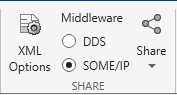
Together with service versioning, these identifiers enable software components to discover and communicate with the correct services at runtime. For more information about configuring service deployment properties on software component ports, see Configure AUTOSAR Adaptive Service Interface Identifier and Configure AUTOSAR Adaptive Service Instance Identifier. To select a network binding for your software architecture, on the Modeling tab, in the Share section, select DDS or SOME/IP. By default, AUTOSAR Adaptive software architectures are configured for SOME/IP middleware. The network binding configuration of the software architecture is automatically applied by the software to all referenced software components and compositions in the software architecture model.
To configure service IDs for software component ports, select a service port on a component boundary in the architecture canvas. In the Property Inspector, expand the Parameters section, and select Deployment. For example, in my_adaptive_BrakeControlSystem select server port Velocity on the component boundary of the Speedometer component. In the Property Inspector navigate to the Deployment tab. Example model my_adaptive_BrakeControlSystem is configured for SOME/IP network binding so the configurable deployment properties are:
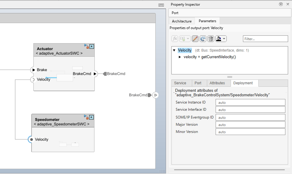
Additional deployment properties depend on the selected network binding and software architecture element. Refer to this table for a complete list of deployment attributes.
Selected Software Architecture Element | DDS Network Binding | SOME/IP Network Binding |
|---|---|---|
Software Component | Application ID Log Mode Log File Path | Application ID Log Mode Log File Path |
Function Ports (client-server) | Service Instance ID Service Interface ID DDS Domain ID | Service Instance ID Service Interface ID SOME/IP Eventgroup ID Major Version Minor Version |
Data ports (receiver) | Service Instance ID Service Interface ID DDS Domain ID | Service Instance ID Service Interface ID SOME/IP Eventgroup ID Major Version Minor Version |
Data ports (sender) | DDS Topic Name | Service Instance ID Service Interface ID SOME/IP Eventgroup ID Major Version Minor Version |
If you leave deployment properties empty, automatic values are assigned when you build the model. The deployment properties allow deployed applications to automatically communicate without any manual configuration. If you do edit the deployment properties then the connected software components are automatically updated by the software to stay consistent. This example uses the automatic values assigned by the software.
Export ARXML and Generate C++ Code from AUTOSAR Adaptive Software Architecture
In a single build action, you can export ARXML descriptions of compositions and components as well as generate algorithmic and service C++ code from an AUTOSAR Adaptive software architecture. You can build an AUTOSAR Adaptive software architecture model in these ways:
From the Modeling toolstrip, in the Share section, click Generate Code and Export ARXML.
Programmatically by using the
slbuildfunction.
slbuild("my_adaptive_BrakeControlSystem");
When you build an AUTOSAR Adaptive software architecture the software generates these outputs in a generic folder structure. The software saves build outputs in a folder with the same name as the software architecture model, in this example, the software saves the build outputs to folder my_adaptive_BrakeControlSystem/. This folder contains subfolders for each referenced software component model and its generated artifacts, in this example: Actuator/, Controller/, Sensors/, and Speedometer/. Alongside the software component, exists a stub/ folder containing files that describe the machine manifest and deployment configuration for the software architecture.
The software also saves the exported composition ARXML descriptions that describe AUTOSAR software composition corresponding to the software architecture, the AUTOSAR Adaptive Service Interfaces, data types, and build and deployment configurations. The exporter automatically creates an Architecture Export report that you can use to view the exported ARXML files. For example, view the SERVICE-INTERFACE definitions and the associated namespace configurations for the software composition by selecting my_adaptive_BrakeControlSystem_interface.arxml.
ARXML Composition Files | Contents |
|---|---|
| AUTOSAR software composition describing connections between components and compositions as they are modeled in the software architecture. |
| AUTOSAR Adaptive Service Interface definitions including the port interfaces defined in the data dictionary: |
| Data type definitions used across the architecture. |
| ARXML software composition description for the |
| Defines execution machine, its mode declarations, process-to-machine mappings, and diagnostic logging and tracing configurations for each component referenced by the composition. |
The exported ARXML software component descriptions are exported alongside their execution and service instance manifest files. This table shows the ARXML files exported for each AUTOSAR Adaptive software component, as well as the corresponding JSON file which is generated for each instance of an AUTOSAR Adaptive software component. For example if you have two Adaptive Component blocks that reference the same software component model then only one set of ARXML files is generated for the referenced software component, while a JSON file is generated for each Adaptive Component block that references that model.
ARXML Component and Manifest Files | Contents |
|---|---|
| ARXML descriptions of each adaptive software component, including AUTOSAR Adaptive Service Interface definitions with ports and events. |
| Application service interface and deployment configurations. Consistent with |
| Defines the SOME/IP or DDS service communication bindings. Consistent with |
| Application service interface and deployment configurations. Consistent with ExecutionManifest.arxml |
| Maps each port to its middleware configuration, including service IDs, event IDs, eventgroup IDs, and QoS settings. Consistent with ServiceInstanceManifest.arxml |
| SOME/IP middleware binding configuration. |
The JSON manifest files configure how each component deploys to a target machine. You can customize these files for your specific network topology and middleware configuration without modifying the algorithmic code. The execution manifest defines the runtime identity of each component. It specifies the process name, application ID, log mode (console, file, or network), and a log description string. The AUTOSAR Adaptive platform uses these values to manage application lifecycle and diagnostic logging.
The service instance manifest maps the architecture-level port connections to concrete SOME/IP service bindings. For the Actuator component, the Velocity required port is bound to service ID 26020 with a getCurrentVelocity method, and the BrakeCmd provided port is bound to service ID 11255 with a Cmd event. This is where the architecture port BrakeCmd from the architecture model becomes an addressable network service. For example, this is the JSON description of architecture port BrakeCmd.
  "ProvidedPorts": [
    {
      "Name": "BrakeCmd",
      "InstanceSpecifier": "adaptive_ActuatorSWC/adaptive_ActuatorSWC_RootSwComponentPrototype/BrakeCmd",
      "InstanceID": "11255",
      "CommunicationMiddleware": "SOMEIP",
      "ServiceID": "11255",
      "MajorVersion": 0,
      "MinorVersion": 0,
      "SOMEIP_EventGroupID": 11255,
      "Data": [
        {
          "Name": "Cmd",
          "SOMEIP_EventID": 58740
        }
      ],
The vsomeip configuration completes the deployment picture with transport-level details. It specifies the unicast address (127.0.0.1 for local simulation), assigns the application a hex ID, defines services with reliable or unreliable transport ports, and maps events to event groups. You would modify these values when deploying to real hardware with multiple ECUs on a network.
The build process generates C++ code that separates algorithmic logic from service code. The services header file declares the communication functions that bridge between the two layers. For the Actuator component, these are: get_Brake_Cmd (receives brake commands), set_BrakeCmd_Cmd (sends brake commands), and call_Velocity_getCurrentVelocity (calls the speedometer service). These functions are called by the algorithm code while their implementations exist in the generated service code. For example, in services header file adaptive_ActuatorSWC_services.h it contains declarations of the receiver, sender, and client service interfaces in the model.
/* receiver service interfaces */
extern SlSignalStatus get_Brake_BrakeCmd(bool *Brake_BrakeCmd_value);
extern SlSignalStatus get_Brake_Cmd(bool *Brake_Cmd_value);

/* sender service interfaces */
extern void set_BrakeCmd_BrakeCmd(bool rtu_BrakeCmd_BrakeCmd_value);
extern void set_BrakeCmd_Cmd(bool rtu_BrakeCmd_Cmd_value);

/* client service interfaces */
extern SlSignalStatus call_Velocity_getCurrentVelocity(double *velocity);
The algorithmic code uses these service interface functions and has no knowledge of SOME/IP service IDs, transport ports, or network addresses. This separation means you can retarget the deployment configuration by changing service IDs, changing the configured middleware, move to different hardware, or switch to a different target platform like Embedded Linux without changing the algorithmic code.
See Also
Software Composition | Adaptive Component
Topics
- Create AUTOSAR Architecture Models
- Add and Connect AUTOSAR Components and Compositions
- Define AUTOSAR Component Behavior by Creating or Linking Models
- Configure and Export ARXML from AUTOSAR Classic Software Architectures
- Verify AUTOSAR Adaptive Software Component Code With SIL
- Configure and Export ARXML from AUTOSAR Adaptive Software Architectures

