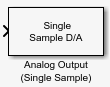
Analog Output (Single Sample)
Output single sample to multiple analog channels of data acquisition device
Libraries:
Data Acquisition Toolbox
Description
The Analog Output (Single Sample) block opens, initializes, configures, and controls an analog data acquisition device. The opening, initialization, and configuration of the device occur once at the start of the model execution. The block outputs a single sample every time step, synchronously to the hardware, during the model run time.
The block has one or more input ports, depending on the option you choose in its dialog box. It has no output ports. The valid data type of the signal at the input port is double.
The Analog Output (Single Sample) block inherits the sample time from the driving block connected to the input port. Analog output is done synchronously, according to the following diagram.
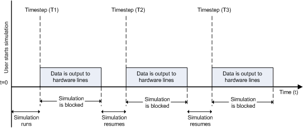
At the first time step (T1), data is output to the selected hardware channels. The simulation does not continue until data is output to all channels.
Notes
To use this block, you need both Data Acquisition Toolbox™ and Simulink® software.
You can use the Analog Output (Single Sample) block only with devices that support single sample output. To send data using devices that do not support acquisition of a single sample (such as devices designed for sound and vibration), use the Analog Output block.
Some devices are not supported by the Simulink blocks in Data Acquisition Toolbox. To see if your device supports Simulink, refer to Supported Hardware.
Other Supported Features
This block supports the use of text accelerator mode, but not Rapid Accelerator or code generation.
The block supports the use of model referencing, so that your model can include other Simulink models as modular components.
For more information on these features, see the Simulink documentation.
Ports
Input
Parameters
Version History
Introduced in R2016b