Lowpass Filter
Design FIR or IIR lowpass filter
Libraries:
DSP System Toolbox /
Filtering /
Filter Designs
Description
The Lowpass Filter block independently filters each channel of the input signal over time using the filter design specified by the block parameters. You can control whether the block implements an IIR or FIR lowpass filter using the Filter type parameter. You can specify the passband and stopband edge frequencies in Hz or in normalized frequency units (since R2023a).
This block supports ARM® Cortex® code generation. Under certain conditions, this block also supports SIMD code generation. For details, see Code Generation.
Examples
Lowpass filter a sinusoidal signal using the Lowpass Filter block. Plot the spectrum of the original signal and the filtered signal in the spectrum analyzer.
Open and inspect the LowpassFilterSinusoid.slx model. The input is a noisy sinusoidal signal with tones at 1 kHz and 15 kHz. The sample rate of the input signal is 44.1 kHz. The added noise is white Gaussian with a mean of 0 and a variance of 0.05.
The lowpass filter is a minimum-order filter that has a passband-edge frequency of 8 kHz and a stopband-edge frequency of 12 kHz. Specify the sample rate of the input signal in the block dialog box.
Run the model and view the filtered output in the spectrum analyzer. The tone at 1 kHz is unaffected while the tone at 15 kHz is attenuated.


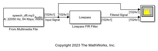
Filter all frequencies above 5 kHz from an audio signal whose sample rate is fixed but not known.
Open and inspect the LowpassFilterAudioSignal.slx model. The input is a speech signal whose sample rate is unknown. The Lowpass Filter block has a passband-edge frequency of 5 kHz. The Sample rate mode parameter in the block dialog box is set to Inherit from input port by default so that the block inherits the sample rate of the speech signal from its input port.
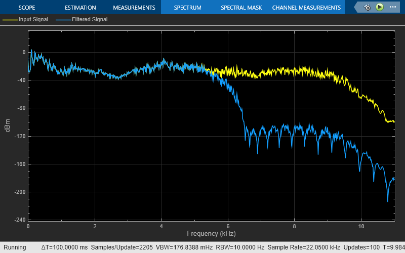
Run the model. View the spectrum of the input signal and the filtered output in the spectrum analyzer.
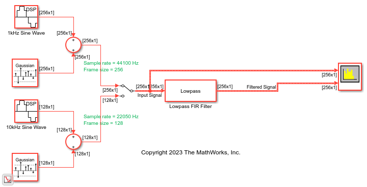
Lowpass filter a sinusoidal signal whose sample rate and frame size vary during simulation.
Open and inspect the LowpassFilterVarSizeSinSignal.slx model. The input can be one of the two sinusoidal signals. The first sinusoidal signal is a 1 kHz sine wave with a sample rate of 44100 Hz and a frame size of 256. The second sinusoidal signal is a 10 kHz sine wave with a sample rate of 22050 Hz and a frame size of 128. The frame period of both the signals is the same (256/44100 or 128/22050). For more information on sample rate and frame period, see Sample- and Frame-Based Concepts. Using a manual switch, you can control which sine wave is input to the Lowpass Filter block.
Since the input sample rate varies during simulation, specify the frequency specifications of the Lowpass Filter block in normalized frequency units. In order to do that, set the Sample rate mode parameter in the Lowpass Filter block dialog box to Use normalized frequency (0 to 1). Now set the passband edge frequency of the lowpass filter to 0.5 in normalized frequency units.
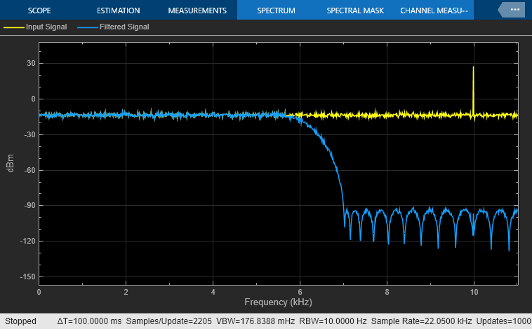
Run the model. View the spectrum of the input and the filtered output in the spectrum analyzer.

This is the filtered output when you select the second sinusoidal signal.
Extended Examples

Obtain Measurements Data Programmatically for Spectrum Analyzer Block
Obtain measurements data from Spectrum Analyzer block.
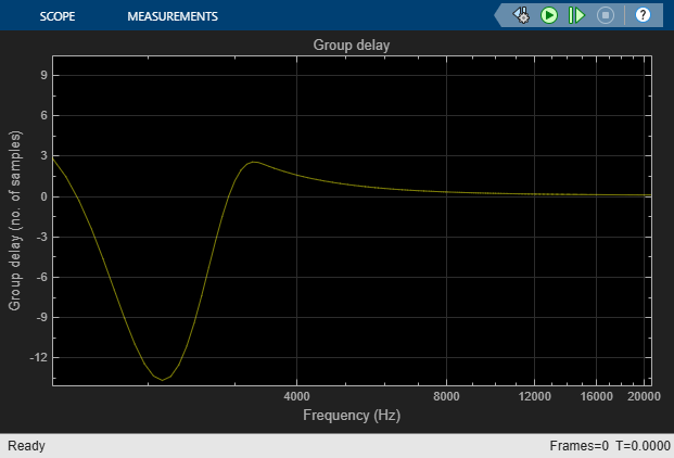
Group Delay Estimation in Simulink
Estimate the group delay of a filter in Simulink®.
Ports
Input
Output
Parameters
Main
Specify whether the block implements an FIR lowpass filter or an IIR lowpass filter.
When you select this check box, the block designs a filter with the minimum order and the specified passband, stopband frequency, passband ripple, and stopband attenuation.
When you clear this check box, you can specify the Filter order as a positive integer.
Specify the filter order of the lowpass filter as a positive integer.
Dependencies
To enable this parameter, clear the Design minimum order filter check box.
Specify the passband edge frequency of the lowpass filter as a real positive scalar in Hz or in normalized frequency units (since R2023a).
If you set the Sample rate mode parameter to:
Specify on dialogorInherit from input port— The value of the passband edge frequency is in Hz and must be less than half the value of the input sample rate.Use normalized frequency (0 to 1)— The value of the passband edge frequency is in normalized frequency units. The value must be a positive scalar less than1.0.
(since R2023a)
Specify the stopband edge frequency of the lowpass filter as a real positive scalar in Hz or in normalized frequency units (since R2023a).
If you set the Sample rate mode parameter to:
Specify on dialogorInherit from input port— The value of the stopband edge frequency is in Hz and must be less than half the value of the input sample rate.Use normalized frequency (0 to 1)— The value of the stopband edge frequency is in normalized frequency units. The value must be a positive scalar less than1.0.
(since R2023a)
Dependencies
To enable this parameter, select the Design minimum order filter check box.
Specify the maximum ripple of the filter response in the passband as a real positive scalar in dB.
Specify the minimum attenuation in the stopband as a real positive scalar in dB.
Since R2023a
Specify the input sample rate using one of these options:
Use normalized frequency (0 to
											1)
— Specify the passband edge and the stopband edge frequencies in normalized frequency units (0 to 1).Specify on dialog— Specify the input sample rate in the block dialog box using the Input sample rate (Hz) parameter.Inherit from input port— The block inherits the sample rate from the input signal.
Specify the input sample rate as a scalar in Hz.
Dependencies
To enable this parameter,
set the Sample rate mode parameter to
Specify on dialog. (since R2023a)
Opens the Filter Visualization Tool (fvtool) and displays the
magnitude and phase response of the Lowpass Filter. The
response is based on the block dialog box parameters. Changes made to
these parameters update FVTool.

To update the magnitude response while FVTool is running, modify the dialog box parameters and click Apply.
Type of simulation to run:
Interpreted execution(default)Simulate model using the MATLAB® interpreter. This option shortens startup time but has slower simulation speed than
Code generation.Code generationSimulate model using generated C code. The first time you run a simulation, Simulink® generates C code for the block. The C code is reused for subsequent simulations, as long as the model does not change. This option requires additional startup time but provides faster simulation speed than
Interpreted execution.
Data Types
Rounding method for the output fixed-point operations.
Fixed-point data type of the coefficients, specified as one of the following:
fixdt(1,16)— Signed fixed-point data type of word length16, with binary point scaling. The block determines the fraction length automatically from the coefficient values in such a way that the coefficients occupy maximum representable range without overflowing.fixdt(1,16,0)— Signed fixed-point data type of word length16and fraction length0. You can change the fraction length to any other integer value.<data type expression>— Specify the data type using an expression that evaluates to a data type object, for example, numeric type (fixdt([ ],16,15)). Specify the sign mode of this data type as[ ]ortrue.Refresh Data Type— Refresh to the default data type.
Click the Show data type assistant
button ![]() to display the data type assistant,
which helps you set the data type. For more information, see Specify Data Types Using Data Type Assistant (Simulink).
to display the data type assistant,
which helps you set the data type. For more information, see Specify Data Types Using Data Type Assistant (Simulink).
Block Characteristics
Data Types |
|
Direct Feedthrough |
|
Multidimensional Signals |
|
Variable-Size Signals |
|
Zero-Crossing Detection |
|