LMS Filter
Libraries:
DSP HDL Toolbox /
Filtering
Description
The LMS Filter block estimates the filter weights and minimizes the error between a desired signal and an observed signal using the mean squared error (MSE) criteria. The block adapts its weights until the error between the data and the desired data is minimal. The block accepts scalar and vector inputs of type real and complex.
You can use this block for various applications, such as noise cancellation, system identification, and inverse system modeling. The block provides an architecture suitable for HDL code generation and hardware deployment.
Note
You can also generate HDL code for this hardware-optimized algorithm, without creating a Simulink® model, by using the DSP HDL IP Designer app. The app provides the same interface and configuration options as the Simulink block.
Examples
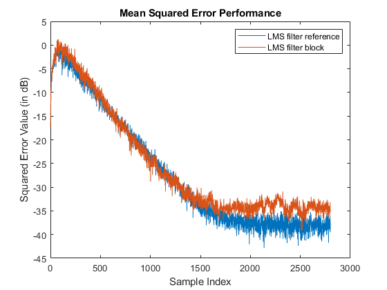
Calculate Mean Square Error Performance Using LMS Filter
How use the LMS Filter block to calculate the mean square error performance in additive white Gaussian noise (AWGN). The block supports scalar and vector inputs of type real or complex. You can generate the HDL code from the LMSFilter subsystem in this Simulink® model.
Ports
Input
Output
Parameters
Algorithms
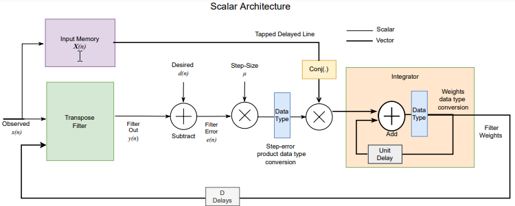
The following figure shows the high-level architecture block diagram of the LMS Filter block for a scalar input. An observed signal is provided as input to the Input Memory block and also to the Transpose Filter block, which is configured with a Discrete FIR Filter block. The output of the Transpose Filter block is subtracted from the Desired input signal to output the Filter Error signal. The Filter Error signal is multiplied with the Step-Size input signal and the resulted step-error product is converted to the required data type. The step-error product is multiplied with the corresponding tap delay line conjugate from the Input Memory block. In the Integrator block, the multiplied output is added to the previous weight, Unit Delay, to output new filter weights. These filter weights are routed back to the Transpose Filter block for the next weight updates.
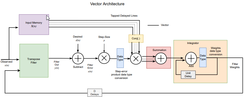
The following figure shows the high-level architecture block diagram of the LMS Filter block for vector input. The vector architecture is almost similar to the scalar architecture. In the vector architecture, step-error product vectors are multiplied with the corresponding tap delay line conjugates from the Input Memory block and then summed up in the Summation block. In the Integrator block, the summed output is added to the previous weight vector Unit Delay to output new filter weights. These filter weights are routed back to the Transpose Filter block for the next weight updates.
For hardware implementation, all these operations are pipelined, which takes around D number of delays to update the filter weights, where D is the latency of the block.
The latency of the block varies with the input size and complexity.
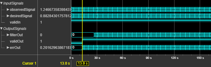
This figure shows the output of the block for a real scalar input when you set the
Filter length parameter to 64 and all
other parameters to their default values. The latency of the block is 13 clock
cycles.
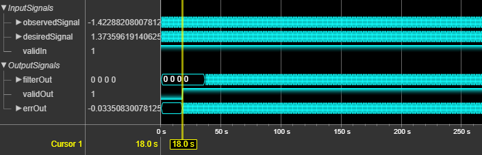
This figure shows the output of the block for a 4-by-1 real vector input when you set
the Filter length parameter to 64 and all
other parameters to their default values. The latency of the block is 18 clock
cycles.
References
[1] Hayes, M.H. Statistical Digital Signal Processing and Modeling. New York: John Wiley & Sons, 1996.
Extended Capabilities
Version History
Introduced in R2023a