Serial Configuration for Monitor & Tune and PIL for STM32 Processor-Based Boards
To prepare your model for Monitor & Tune (External mode) or PIL with serial communication.
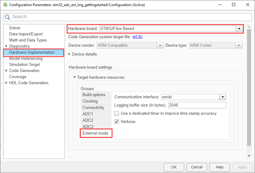
In the Configuration Parameters dialog box, select Model Configuration Parameters > Hardware Implementation.
Select a STM32F4xx Based processor from the Hardware board drop-down list.
Under Target Hardware Resources, select External mode.
In Communication interface drop-down list, select
Serial.Specify the Logging buffer size in bytes. Ensure that the logging buffer size is large enough if you are logging more number of signals or logging at faster rates.
Enable the Use a dedicated timer to improve time stamp accuracy parameter if you want to use dedicated timer to log data in real time. If this parameter is not selected, data is logged with simulation time.
Note
To use Display and Scope blocks in a model, ensure that the Use a dedicated timer to improve time stamp accuracy parameter is disabled.
Make sure that the Verbose check box is selected to view the external mode execution progress and updates in the Diagnostic Viewer or in the Command Window.
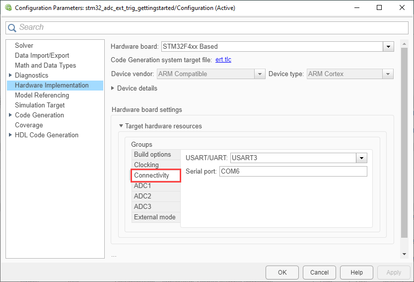
Go to Connectivity and select USART/UART.
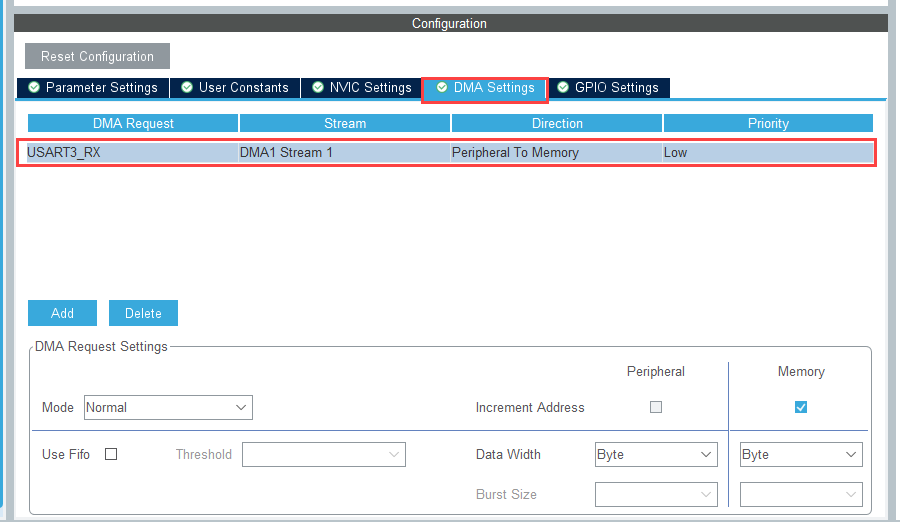
For the selected USART/UART, ensure that the Desired baud rate in bits/sec, Mode and DMA settings are configured in STM32CubeMX project. Open the STM32CubeMX project and perform the following configuration:
Set the USART/UART Mode to
Asynchronous.Specify the desired Baud Rate in bits/sec.
Note
Higher baud rates allow data logging at faster rates.
Add DMA request for USART receive under DMA settings.
The hardware board has USART pins connected to ST-LINK. To run the model in External mode, ensure to configure the GPIO settings for USART. For more information on USART pins connected to the ST-LINK, refer to the respective board's schematic diagram.
Save the project file.
Note
For External mode and PIL to be successful, perform the above configuration in STM32CubeMX project and import the
.iocproject file. For more, see Configure STM32 Processor-Based Boards using STM32CubeMX with Simulink.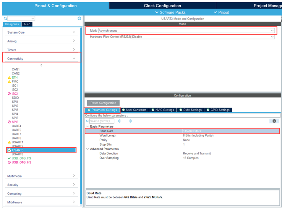

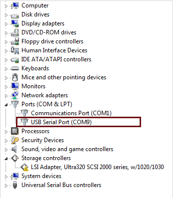
Specify the corresponding COM port that the target hardware uses.
To see the list of available COM ports on your computer, select Start > Control Panel > Device Manager > Ports (COM & LPT).
Your model is now ready to perform Monitor and Tune action (External Mode) over serial communication.
See Also
Configure STM32 Processor-Based Boards using STM32CubeMX with Simulink
Topics
- Monitoring and Tuning Using STMicroelectronics STM32 Processor Based Boards
- Code Verification and Validation with PIL for STMicroelectronics STM32 Processors Based Boards
- Getting Started with STMicroelectronics STM32 Processor Based Boards
- Using the Analog to Digital Converter Block to Support STMicroelectronics STM32 Processor Based Boards