Configure Root-Level Model Ports with Receiver and Sender Service Interface Definitions
R2026bConfigure Communication and Execution Behavior of Software Components
Components in a service-oriented system exchange data over a middleware network such as DDS or SOME/IP. Receiver and Sender services are platform-provided functions called by the code generated from the model, implementing receiver and sender port elements (modeled as In Bus Element and Out Bus Element block elements, respectively). Each sender port element invokes a sender service function to send data to the receiver on another component, and the receiver port element invokes the receiver service function to receive the data. The data elements are stored in the communication layer, which is managed by the platform.
Before generating code from your model, use the Service Mappings editor to map Out Bus Element blocks to sender services and In Bus Element blocks to receiver services.
Map Root-Level Model Ports to Sender and Receiver Service Interface Definitions
In this example you map sender and receiver port elements to sender and receiver service interface definitions, respectively. You do that by configuring the service definitions for each port.
Open and Explore Architecture System
Open the architectural system SWArch.
soaArchSystem = "SWArch";
open_system(soaArchSystem)
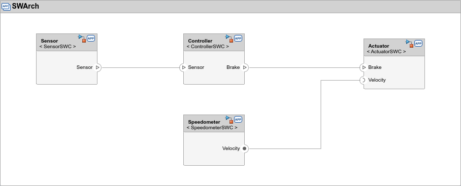
The sender port, Sensor, in the model SensorSWC is connected to the receiver port, Sensor, in the model ControllerSWC.
Open and Explore Component Models
Open the component model ControllerSWC as top model.
soaControlModel = "ControllerSWC";
open_system(soaControlModel)
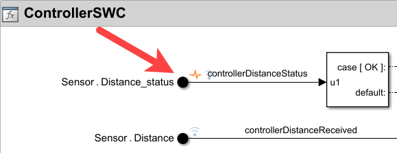
For the example, delete the input port Sensor.Distance_status. Later in the example you re-add this port.
Open the component model SensorSWC as top model.
soaSensorModel = "SensorSWC";
open_system(soaSensorModel)
Open Service Mappings Editors
For each model, open the Service Mappings editor. In the sensor model, select the Senders tab of the editor and in the controller model, select the Receivers tab.
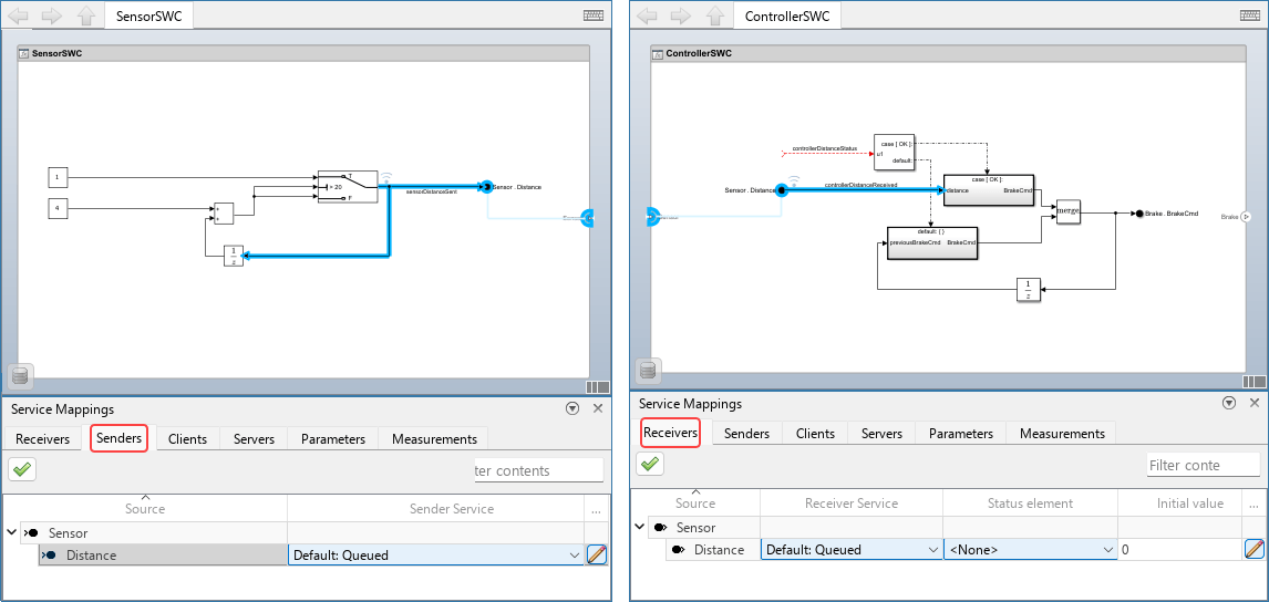
In the sensor model the parent entry in the spreadsheet corresponds to the Out Bus Element Sensor, and in the controller model the parent entry corresponds to the In Bus Element Sensor. The foldable child elements correspond to single signal port elements in them.
Configure Sender Service and Receiver Service
The Sender Service property in the sender and the Receiver Service property in the receiver define whether the service is queued or not. Corresponding sender and receiver ports must match. When the service is queued, data elements from the sender are kept in a queue and delivered to the receiver in turn. (The queue type is a standard first-in-first-out.) When the service is not queued, only the last sent data element is saved. Any older data element that has not been delivered to the receiving port element is discarded upon arrival of a new element from the sender.
The queue is stored in the platform and managed by it, but the behavior of the sender and receiver need to be adjusted to the service type because queued communication method is conceptually different from a non queued method. With non queued communication method it is more likely that some data elements end up not being used, and both the sender and receiver must be aware of that and behave accordingly.
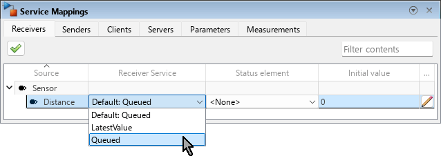
In the example, use the Service Mappings editor to map the Distance port element of each component to a queued service interface:
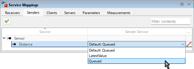
For the sensor component: in the Senders tab of the Service Mappings editor, locate the child entry
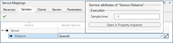
Distanceunder the parent entrySensor. Then, from the list in the Senders Service column, select Queued.
For the controller component: in the Receivers tab of the Service Mappings editor, locate the child entry
Distanceunder the parent entrySensor. Then, from the list in the Receiver Service column, select Queued.
Status Element
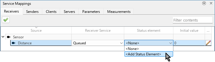
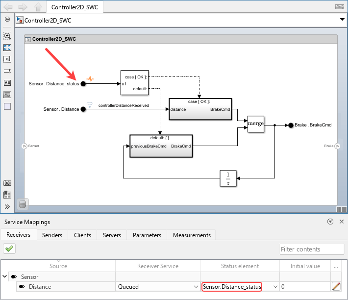
In the receiver, a Status Element is an additional, optional port element of the same In Bus Element block. Use a status element to detect and handle communication conditions such as data not arriving on time and dropped server connections. The status element uses the built-in Simulink enumeration data type SlSignalStatus to handle communication health. A data port element can map to one status port element, and a status port element cannot be used as a data port element or as the status port element of another data port element. Use a status element when you want the behavior of the model to depend on the delivery status. For example, in this model you have two conditionally executed subsystems: the upper subsystem is designated to execute when the signal status is OK (meaning the signal has been successfully delivered), and the lower subsystem is designated to execute otherwise.
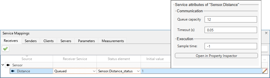
Add a status element to the Distance port element: in the Status Element column for the receiver port Distance, from the list, select <Add Status Element>.
A new port element is created. Locate it on the model canvas and connect it to the input port of the Switch Case block. Because the new port serves as a status element, it has no entry of its own in the table.
Receiver Initial Value
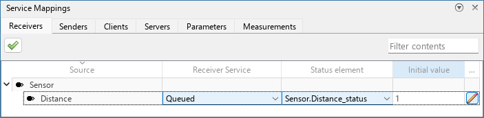
A fallback value to use before receiving the first valid value from the sender. This value is used if the receiver port is not connected, the sender port is not yet initialized, or is initialized but has not yet sent any data. It prevents unpredictable errors stemming from using values of uninitialized variables. The dimensions of the initial value must be compatible with the port element signal dimensions. The default value for this property, in case you do not specify it, is a zero-filled array with the dimensions of the signal.
Here, specify the Initial value of the distance as 1.
Configure Receiver Service Properties in Additional Properties Dialog Box
Some receiver service properties do not appear in the spreadsheet. To configure these properties for a specific port, you need to open the dialog box by clicking the pencil icon  at the end of the table entry.
Queue capacity
Use the Queue capacity property with queued receiver services to specify the maximum number of data elements to hold in the queue. When the last value in the queue is delivered, a copy of this data element is saved as a fallback value to deliver in case the port needs to provide a data element before a new one arrives. In such case, the port re-delivers this previous value.
Timeout
The Timeout property to specify the maximum time, in seconds, that is allowed to wait for data element since valid data was last received by the port. When the Timeout value is reached, the status element returns SlSignalStatus.TIMEOUT, and the receiver holds the last valid value that it received from the sender. After that, the receiver service restarts timeout monitoring and continues processing incoming data elements.
Sample time
The Sample time property is only applicable in periodic systems (that must have a fixed-step size in this configuration). This property determines how frequently the receiver reads data and executes. The measurement unit is seconds, but it must be an integer multiple of the fixed-step size of the system.
Valid sample time values are:
-1— Inherit the sample time from the system in which the receiver lives. The generated code reads from the receiver port element once in every system step.positive scalar— Number of seconds between one sampling and the next. The value must be an integer multiple of the fixed-step size of the model. For example, if the value isN*stepSizewhereNis a positive integer andstepSizeis the fixed-step size of the system (in seconds), then the generated code reads from the receiver port element once everyNsystem steps.
On data arrival, execute
This property is only applicable for export-function models. The function-call inports to invoke upon data arrival. A function-call inport can be selected to be called only by one port element. To learn mode about this option, see Configure Components for Data-Triggered Execution.
In the example, specify these values for the properties in the Additional Properties dialog box:
Queue capacity —
12Timeout —
0.05Sample time —
-1On data arrival — N/A because the system is periodic.
Sender Sample Time
The Sample time of the sender must match the Sample time of the corresponding receiver. Use the Additional Properties dialog box to verify that the Sample time of the Sensor.Distance port in the sensor model is -1.
Generate Model Code
Generate code from the sensor model.
evalc("slbuild(soaControlModel,GenerateCodeOnly=true)");
Use the Code pane of the sensor model to see:
The step function,
SensorSWC_step, in the fileSensorSWC.cpp.The function
set_Sensor_Distance, defined in the fileSensorSWC_comm.cpp.
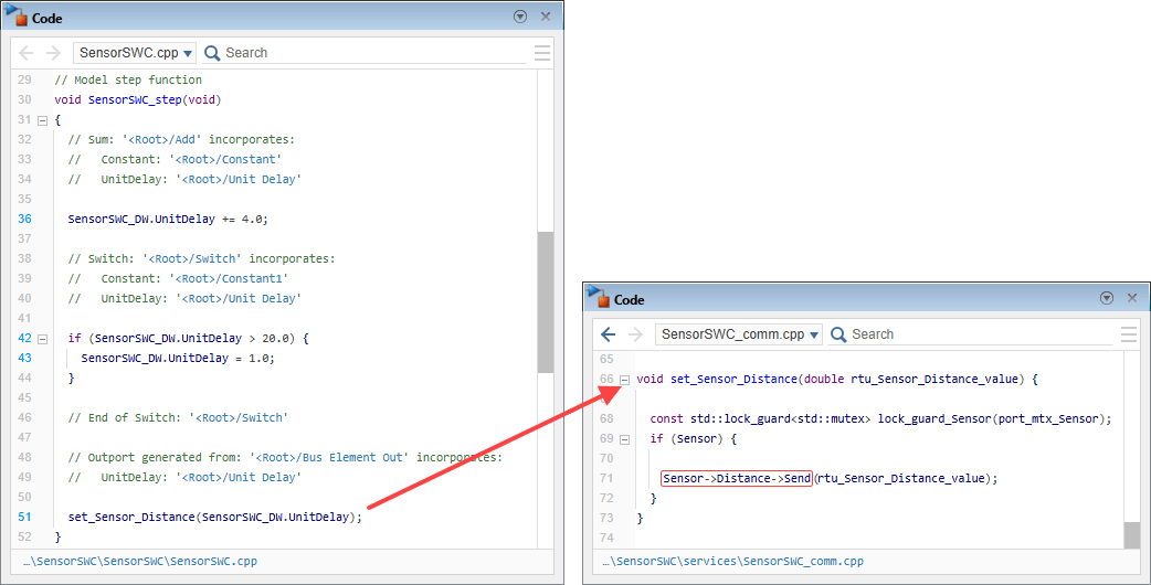
Note that the file SensorSWC_comm.cpp is located at the subfolder services.
Generate code from the controller model.
evalc("slbuild(soaControlModel,GenerateCodeOnly=true)");
Use the Code pane of the controller model to see:
The step function,
ControllerSWC_step, in the fileControllerSWC.cpp.The function
get_Sensor_Distance, defined in the fileControllerSWC_comm.cpp.
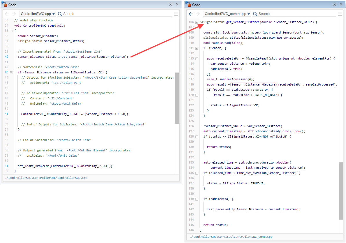
Note that the file ControllerSWC_comm.cpp is located at the subfolder services.
See Also
Service Mappings Editor | Senders Service Interface Properties | Receivers Service Interface Properties

