Get Started with MATLAB to High-Level Synthesis Workflow Using HDL Coder App
R2026bThis example shows how to create an HDL Coder™ project and generate High-Level Synthesis (HLS) code from a MATLAB® design for a symmetric finite impulse response (FIR) filter.
Examine the MATLAB Design
The MATLAB design mlhdlc_sfir is a simple symmetric FIR filter. Open the MATLAB design.
design_name = "mlhdlc_sfir";
testbench_name = "mlhdlc_sfir_tb";
open(design_name);
%%%%%%%%%%%%%%%%%%%%%%%%%%%%%%%%%%%%%%%%%%%%%%%%%%%%%%%%%%%%%%%%%%%%%%%%%%
% MATLAB design: Symmetric FIR Filter
%
% Introduction:
%
% We can reduce the complexity of the FIR filter by leveraging its
% symmetry. Symmetry for an n-tap filter implies, coefficient h0 =
% coefficient hn-1, coefficient, h1 = coefficient hn-2, etc. In this case,
% the number of multipliers can be approximately halved. The key is to add
% the two data values that need to be multiplied with the same coefficient
% prior to performing the multiplication.
%
% Key Design pattern covered in this example:
% (1) Filter states represented using the persistent variables
% (2) Filter coefficients passed in as parameters

%   Copyright 2011-2026 The MathWorks, Inc.

%#codegen
function [y_out, delayed_xout] = mlhdlc_sfir(x_in,h_in1,h_in2,h_in3,h_in4)
% Symmetric FIR Filter

% declare and initialize the delay registers
persistent ud1 ud2 ud3 ud4 ud5 ud6 ud7 ud8;
if isempty(ud1)
    ud1 = 0; ud2 = 0; ud3 = 0; ud4 = 0; ud5 = 0; ud6 = 0; ud7 = 0; ud8 = 0;
end

% access the previous value of states/registers
a1 = ud1 + ud8; a2 = ud2 + ud7;
a3 = ud3 + ud6; a4 = ud4 + ud5;

% multiplier chain
m1 = h_in1 * a1; m2 = h_in2 * a2;
m3 = h_in3 * a3; m4 = h_in4 * a4;

% adder chain
a5 = m1 + m2; a6 = m3 + m4;

% filtered output
y_out = a5 + a6;

% delayed output of input signal
delayed_xout = ud8;

% update the delay line
ud8 = ud7;
ud7 = ud6;
ud6 = ud5;
ud5 = ud4;
ud4 = ud3;
ud3 = ud2;
ud2 = ud1;
ud1 = x_in;
end
Examine the MATLAB Test Bench
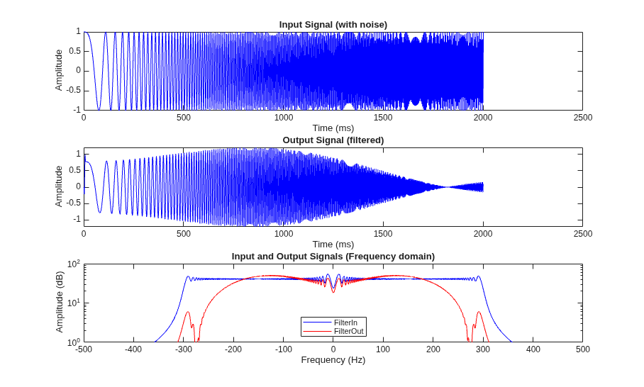
The mlhdlc_sfir_tb test bench defines low-pass filter coefficients and applies a representative input range. The test bench runs the design with these inputs to test the filter response. Open the test bench.
open(testbench_name);
%%%%%%%%%%%%%%%%%%%%%%%%%%%%%%%%%%%%%%%%%%%%%%%%%%%%%%%%%%%%%%%%%%%%%%%%%%
% MATLAB test bench for the FIR filter
%%%%%%%%%%%%%%%%%%%%%%%%%%%%%%%%%%%%%%%%%%%%%%%%%%%%%%%%%%%%%%%%%%%%%%%%%%

%   Copyright 2011-2026 The MathWorks, Inc.
clear mlhdlc_sfir;
T = 2;
dt = 0.001;
N = T/dt+1;
sample_time = 0:dt:T;

df = 1/dt;
sample_freq = linspace(-1/2,1/2,N).*df;

% input signal with noise
x_in = cos(2.*pi.*(sample_time).*(1+(sample_time).*75)).';

% filter coefficients
h1 = -0.1339; h2 = -0.0838; h3 = 0.2026; h4 = 0.4064;

len = length(x_in);
y_out = zeros(1,len);
x_out = zeros(1,len);

for ii=1:len
    data = x_in(ii);
    % call to the design "mlhdlc_sfir" that is targeted for hardware
    [y_out(ii), x_out(ii)] = mlhdlc_sfir(data, h1, h2, h3, h4);
end

figure("Name", string(mfilename) + "_plot");
subplot(3,1,1);
plot(1:len,x_in,"-b");
xlabel("Time (ms)")

ylabel("Amplitude")
title("Input Signal (with noise)")
subplot(3,1,2); plot(1:len,y_out,"-b");
xlabel("Time (ms)")
ylabel("Amplitude")
title("Output Signal (filtered)")

freq_fft = @(x) abs(fftshift(fft(x)));

subplot(3,1,3); semilogy(sample_freq,freq_fft(x_in),"-b");
hold on
semilogy(sample_freq,freq_fft(y_out),"-r")
hold off
xlabel("Frequency (Hz)")
ylabel("Amplitude (dB)")
title("Input and Output Signals (Frequency domain)")
legend({"FilterIn", "FilterOut"},"Location","South")
axis([-500 500 1 100])
Test the MATLAB Design
Verify that mlhdlc_sfir processes a sample stream and produces the expected filter response before generating HLS code. Run the design with mlhdlc_sfir_tb to provide low-pass filter coefficients and stream samples to mlhdlc_sfir.
mlhdlc_sfir_tb
Create an HDL Coder Project
Set the path to your third-party HLS synthesis tool by using the hdlsetuphlstoolpath function.
To create an HDL Coder project and configure it for HLS code generation:
1. In the MATLAB Command Window, run this command to create a project sfir_project and open the HDL Workflow Advisor:
coder -hdlcoder -new sfir_project
2. In the HDL Workflow Advisor task, set Code Generation Workflow to MATLAB to HLS.
3. In the Define Input Types task, add the design and test bench files:
a. For MATLAB Function, click Browse and select mlhdlc_sfir.m.
b. For MATLAB Test Bench, click the + button and select mlhdlc_sfir_tb.m.
4. Click Run in the Define Input Types task. The HDL Workflow Advisor runs the test bench to infer the input data types of the MATLAB design mlhdlc_sfir.
Create a Fixed-Point Version of the MATLAB Design
Convert floating-point data types in the MATLAB design to fixed-point data types.
In the Fixed-Point Conversion task:
Click the Analyze Design button to generate an instrumented MEX function for data type range analysis.
Click Type proposal settings, then set Default word length to
14.Click Advanced, then set Safety margin for sim min/max to
10.Right-click the Fixed-Point Conversion task and select Run this task.
For more information on floating-point to fixed-point conversion, see Floating-Point to Fixed-Point Conversion.
Generate HLS Code
To deploy the generated HLS code on a target platform, specify the target and third-party synthesis tool before you generate HLS code.
In the Select Code Generation Target task, set these parameters:
Set Workflow to
Generic ASIC/FPGA.Set Synthesis tool to
Cadence Stratus HLS.
Right-click the HLS Code Generation task and select Run to selected task.
The code generator runs the Workflow Advisor tasks to generate HLS code for the filter design.
To examine the generated HLS code, click the hyperlink to mlhdlc_sfir_fixptClass.hpp in the HLS Code Generation Output Logs pane.
HLS Code Generation Report
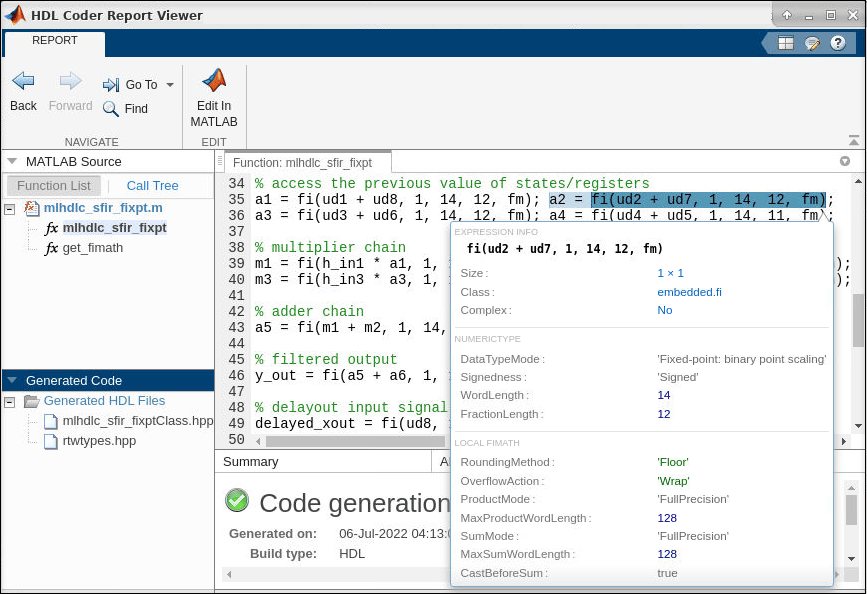
In the HLS Code Generation task, check the code generation report.
Use the code generation report to:
Debug code generation issues and verify that your MATLAB code is suitable for HLS code generation.
View generated HLS code.
Access additional reports, such as a conformance report and resource utilization report.
See how the code generator determines and propagates type information for variables and expressions in your MATLAB code.
To view a MATLAB function in the code pane, click the name of the function in the MATLAB Source pane. When you hover over on a variable or expression, a tooltip displays its size, type, and complexity.
For more information, see HLS Code Generation Report.
Verify and Synthesize the Generated HLS Code
Verify that the generated HLS code produces the same output as the MATLAB code, then synthesize the HLS code to generate RTL code.
In the Verify with HLS Test Bench task:
In the Output Settings tab, select Generate test bench and Simulate generated test bench.
Click Run. This task generates HLS test bench files, creates the Cadence Stratus project, and compares the HLS code output to the MATLAB code output.
To synthesize the HLS code, right-click the Synthesis and Analysis > Run Synthesis task and select Run this task. The HLS tool synthesizes the generated HLS code and generates Verilog or VHDL code.
Limitations
Cadence Stratus HLS supports only point-to-point (p2p) communication for HLS code generation.
HDL Coder does not support generating HLS code that runs on multiple threads.
HDL Coder does not support arrays of structures, enumerations, and classes as inputs and outputs at the top-level DUT ports for HLS code generation.
See Also
Workflow Advisor | coder.HlsConfig | hdlsetuphlstoolpath

