System Design with HDL Code Generation from MATLAB and Simulink
R2026bThis example shows how to generate a Simulink® model and MATLAB Function block from a MATLAB® algorithm. You can then generate HDL code from this model.
HDL Coder™ can generate HDL code from both MATLAB and Simulink. When you generate HDL code for a function in MATLAB, you can also generate a Simulink model and a MATLAB Function block from your MATLAB code. Use this capability to integrate your MATLAB algorithm into a Simulink model. You can then simulate and optimize the complete system, generate HDL code from the model, and program an FPGA with the entire design.
In this example, you generate a MATLAB Function block from MATLAB code that models an FIR filter.
Examine the MATLAB Design and Test Bench
Set up the MATLAB function and test bench for this example. In the MATLAB Command Window, enter:
mlhdlc_demo_setup("mlhdlc_fir");The MATLAB function, mlhdlc_fir, implements a 16-tap FIR filter. The
function stores filter coefficients in a constant array and uses a persistent variable to
maintain a tap delay line. On each call, the function computes the sum of products between
the delay line and the coefficients, then shifts the delay line by one sample.
To view the function, enter:
open mlhdlc_fir.m;The test bench, mlhdlc_fir_tb, exercises the filter by passing 200
samples of a noisy sinusoidal signal through the design and plotting the input and filtered
output. To view the test bench,
enter:
open mlhdlc_fir_tb.m;Simulate the Design
To check for run-time errors, simulate the design by running the test bench. In the MATLAB Command Window, enter:
mlhdlc_fir_tb;
Generate a Simulink Model from the MATLAB Design
To generate a Simulink model from a MATLAB HDL design, you must have a Simulink license. To verify that Simulink is available, enter:
license("test","Simulink")
1, Simulink is available.Specify the MATLAB function and test bench, then create a fixed-point configuration
object and an HDL configuration object by using the coder.config function. Associate the test bench with both configuration
objects and enable the GenerateMLFcnBlock HDL configuration
property.
designName = "mlhdlc_fir";
designTB = "mlhdlc_fir_tb";
fixptCfg = coder.config("fixpt");
fixptCfg.TestBenchName = designTB;
cfg = coder.config("hdl");
cfg.TestBenchName = designTB;
cfg.GenerateMLFcnBlock = true;
Run the floating-point to fixed-point conversion and generate the Simulink model:
codegen("-float2fixed", "fixptCfg", "-config", "cfg", designName);
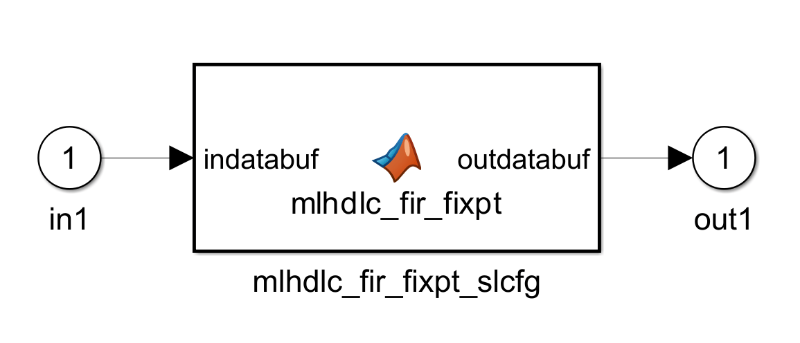
After code generation completes, HDL Coder opens a mlhdlc_fir_fixpt_MLFcnModel Simulink model that
contains a MATLAB Function block representing the fixed-point version of the
MATLAB design. HDL Coder automatically applies settings to the model and MATLAB Function
block so that the model can simulate in Simulink and generate HDL code.
Generate HDL Code from the Simulink Model
To generate HDL code from the generated model, enter:
makehdl("mlhdlc_fir_fixpt_MLFcnModel");You can rename and save the generated model to use in a larger Simulink design, or generate HDL code from the model to program an FPGA.
See Also
makehdl | makehdltb | codegen | coder.config

