Generate SystemVerilog DPI Component from Simscape
This example shows how to generate a SystemVerilog DPI component for an analog circuit that you model with Simscape™ Electrical™. You can then incorporate the generated DPI component into mixed-signal simulation environments for architectural exploration and verification. This workflow enables you to reuse the system-level circuit models and reduce overall debug and verification time.
Introduction
Simscape Electrical is a Simulink® tool for modeling and simulating electrical circuits. It supports a variety of components, including resistors, capacitors, and op-amps, enabling ASIC designers to construct system-level analog mixed-signal (AMS) models for architecture exploration, definition, and refinement.
Traditionally, verification engineers manually develop behavioral models for analog circuits using SystemVerilog Real Number Modeling (SV-RNM) or Verilog-AMS, which is time consuming. Directly generating DPI-C models from Simscape reduces the manual effort and accelerates the simulation process, as DPI-C simulations typically run faster than those using Verilog-AMS. This enhanced efficiency enables earlier verification and reduces overall debug and verification time.
The workflow for generating DPI from Simscape is as follows:
Design the analog circuit using Simscape Electrical.
Simulate the model with the variable-step solver.
Convert the solver to a fixed-step configuration. Adjust the sample time to ensure that the output differences between the fixed-step and variable-step solvers meet your error tolerance.
Generate the DPI component and testbench using HDL Verifier. Verify the DPI component against data vectors from your Simulink subsystem.
Import the DPI component into a mixed-signal verification environment. Perform either digital mixed-signal (DMS) simulation using tools such as Cadence® Xcelium™ Logic Simulator, or analog mixed-signal simulation using tools like Cadence Virtuoso AMS Designer.

Design Analog Circuit Using Simscape
First, use Simscape Electrical components to build an analog circuit model. The DUT in this example is a passive low-pass filter made of a resistor and a capacitor, with a cutoff frequency of 55 kHz. Run these commands to open the example model and initialize the model parameters:
open_system("simscape_dpi");

F = 55e3; % Cutoff frequency
C = 1e-9; % Capacitance value
R = 1 / (2 * pi * C * F); % Resistance value
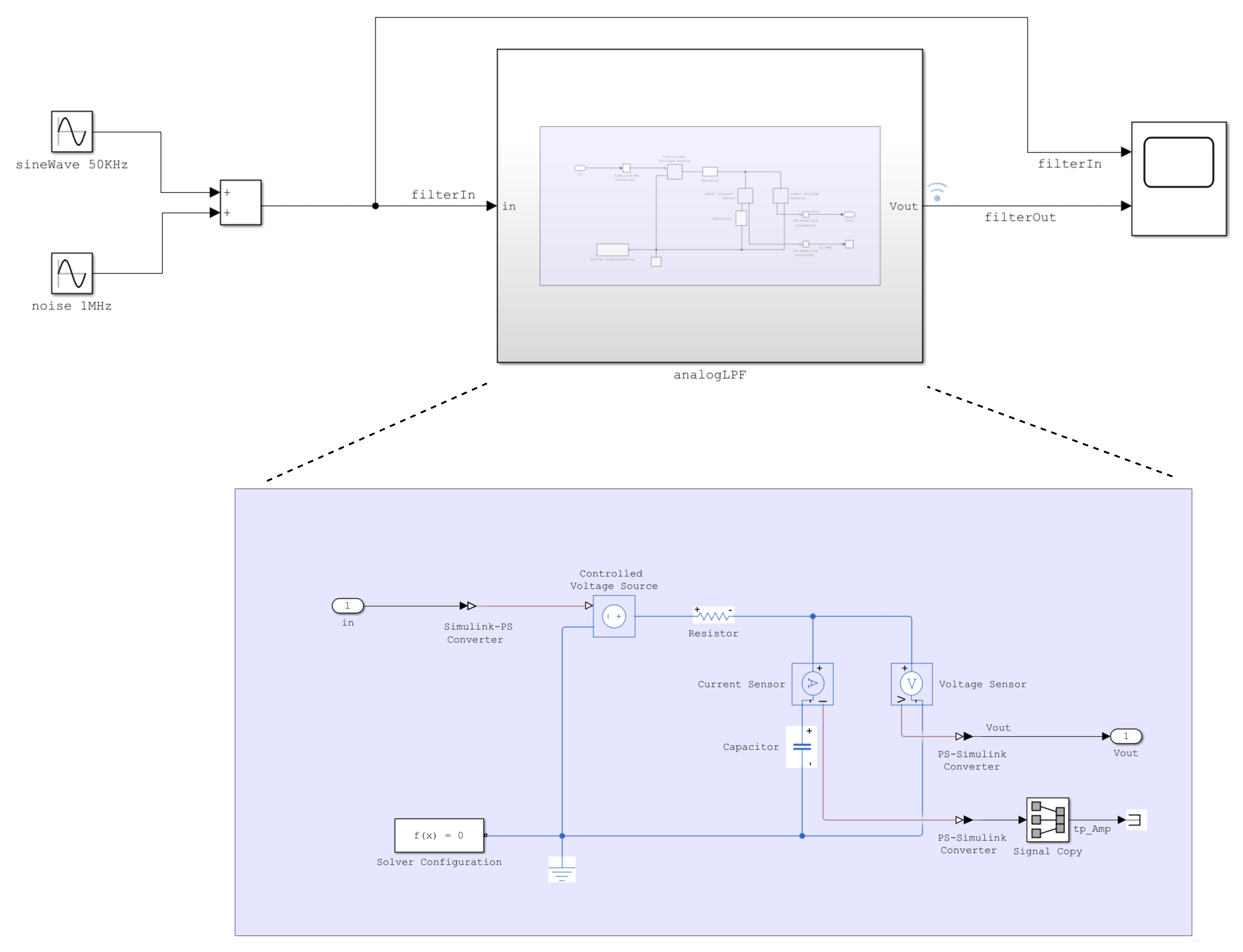
To facilitate C code generation, convert the analog circuit model into the analogLPF subsystem. Then, add testbench inputs and a scope in the digital domain. The filter input consists of a 50 kHz sine wave and a 1 MHz sine wave to simulate high-frequency noise. The filter output signal, filterOut, is marked for logging. The model utilizes a variable-step global Simulink solver. Simulate the model using the following command and open the scope to observe how the filter smooths the input signal by attenuating high-frequency noise.
sim("simscape_dpi");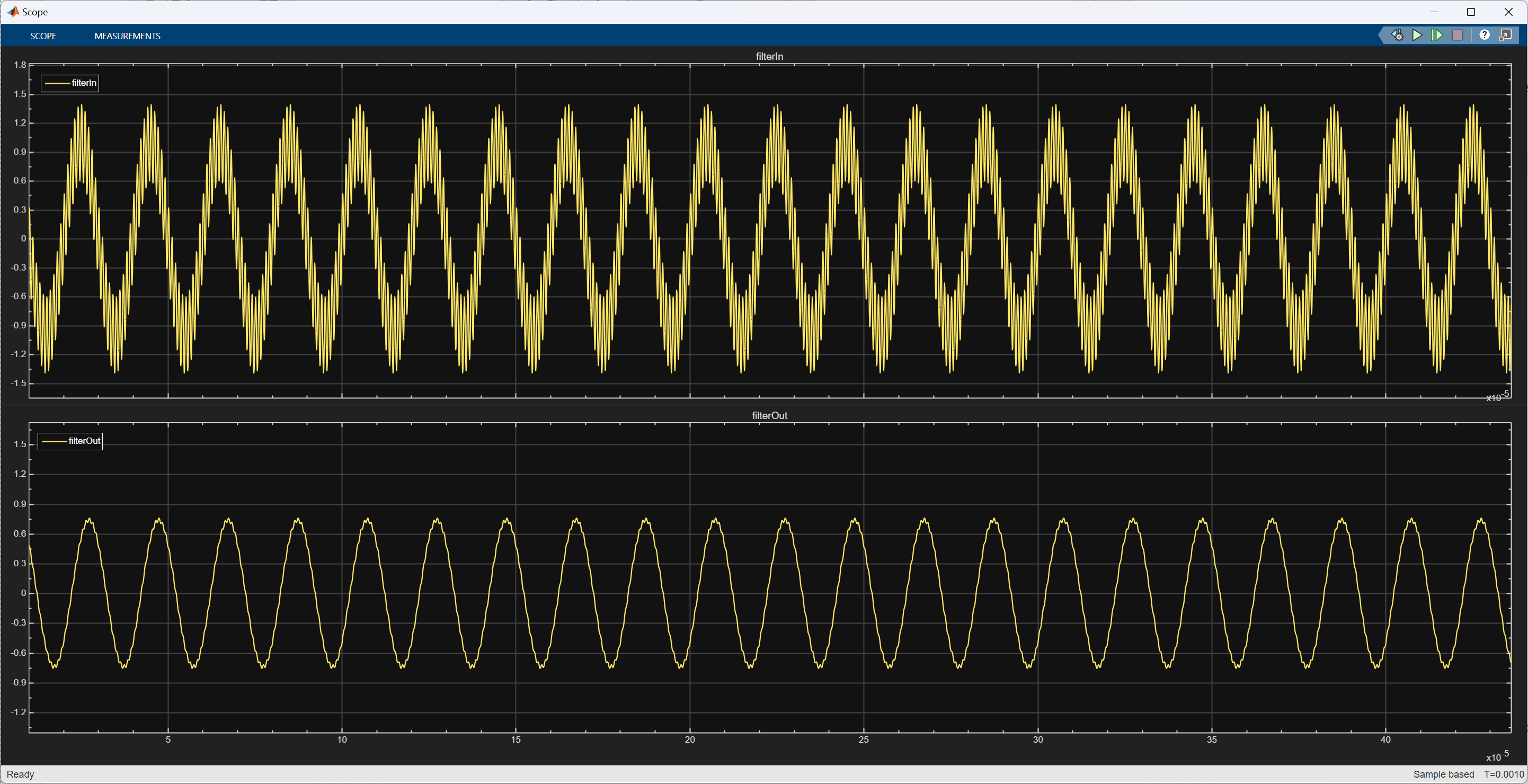
Convert Simscape Variable-Step Model to Fixed-Step Model
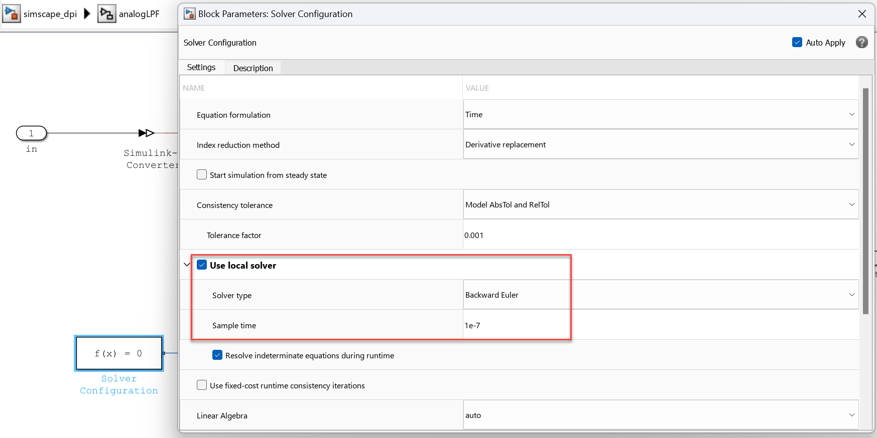
The results from the variable-step simulation serve as the baseline reference. Next, configure the solver to fixed-step, as required for DPI generation. Choosing the appropriate sample time is crucial for translating the model execution from continuous to discrete time. Selecting a smaller sample time allows for a more accurate representation but results in slower simulation speed. You need to minimize errors caused by solver configuration changes to a specified tolerance. You can start with a sample time that corresponds to 10 times the fastest sampling rate of blocks in the model. In this example, the highest sampling rate is 1 MHz (noise sine wave), which results in a sample time of 1/(10*1e6) = 1e-7.
To change the solver configuration to fixed-step:
Open the
Solver Configurationblock in theanalogLPFsubsystem. Select the Use local solver check box. Set the Solver type parameter toBackward Euler. Set the Sample time parameter to1e-7.
Open the Configuration Parameters dialog box, set Type to
Fixed-stepin the Solver pane.
Optionally, run the following commands to change the solver configuration:
set_param("simscape_dpi/analogLPF/Solver Configuration","UseLocalSolver","on");
set_param("simscape_dpi/analogLPF/Solver Configuration","LocalSolverChoice","NE_BACKWARD_EULER_ADVANCER");
set_param("simscape_dpi/analogLPF/Solver Configuration","LocalSolverSampleTime","1e-7");

set_param("simscape_dpi","SolverType","Fixed-step");
After changing the model to use a fixed-step solver, simulate the model again:
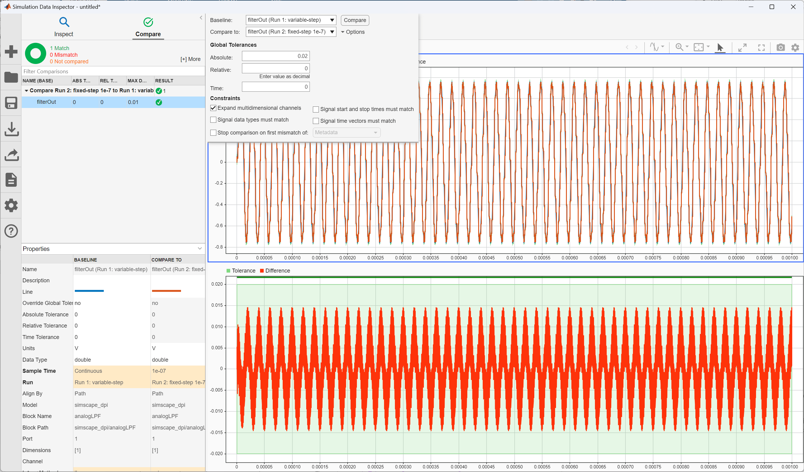
sim("simscape_dpi");To compare the simulation results between the variable-step solver and the fixed-step solver, click Data Inspector on the Simulation tab under Review Results.
Use the variable-step simulation results as the baseline and compare them to the fixed-step simulation. The example specifies an absolute tolerance of 0.02 for demonstration purposes, but you should specify your own tolerance based on the application specifications. If the simulation result shows the error is out of range, decrease the sample time and simulate again until it meets the tolerance. Once the results are satisfactory, you can generate the DPI component.
Generate DPI Components and Testbench
To generate a SystemVerilog DPI component and testbench, open the HDL Verifier app from the Apps tab:
Select DPI Component Generation in the Mode section.
Click the subsystem
analogLPFin the model and in the Map section select Include Testbench.Click SystemVerilog Settings in the Prepare section and set Floating point tolerance to
1e-14.Click Generate DPI Component in the Generate section.
Optionally, run these commands to generate DPI:
set_param("simscape_dpi","SystemTargetFile","systemverilog_dpi_grt.tlc");
set_param("simscape_dpi","DPIGenerateTestBench","on");
set_param("simscape_dpi",'DPIFloatingPointTolerance',1e-14);
slbuild("simscape_dpi/analogLPF");
To verify the generated DPI component against Simulink data using the Cadence Xcelium simulator, run the following command:
cd analogLPF_build/dpi_tb
[~, result] = system("sh run_tb_xcelium.sh")
Incorporate DPI Component into Mixed-Signal Verification Environment
The generated SystemVerilog DPI component supports both digital mixed-signal (DMS) and analog mixed-signal (AMS) simulations. You can incorporate this equivalent behavioral DPI into the mixed-signal simulator and use it as a behavioral model for system simulation and verification. To learn how to import and simulate the DPI component using Cadence Virtuoso AMS Designer, see Generate SystemVerilog DPI for Analog Mixed-Signal Verification.
Debug Internal Signals (Optional)
If you need to access the internal signals of the DUT for debugging from the testbench, such as the current through the capacitor, follow these additional steps before generating DPI components:
Convert current or voltage measured in the physical network into a physical signal using the
Current Sensorblock or theVoltage Sensorblock.Convert the physical signal to a Simulink signal using the
PS-Simulink Converterblock. Then add theSignal Copyblock to preserve signal naming when generating code.Double-click the Simulink signal to enter a signal name, such as
tp_Amp. To mark the signal as a test point and capture the test vector, click Test Point and Log Signals from the Prepare section in the HDL Verifier app.In the Configuration Parameters dialog box, on the Code Generation > SystemVerilog tab, set Generate access function to test point to
One function per Test Point.
The SystemVerilog interface function DPI_simscape_dpi_1029_out_1_tp_Amp is generated and called in the SystemVerilog file.
Tune Parameters During Simulation (Optional)
If you need to simulate the DPI component with tunable parameters, such as the resistance value, follow these additional steps before generating DPI components:
Set Storage class of the parameter to
ExportedGlobal.Double-click the
Resistorblock and set Configurability toRun-time.
R  = Simulink.Parameter(R);
R.CoderInfo.StorageClass = "ExportedGlobal";
The SystemVerilog interface function DPI_analogLPF_setparam_R is generated. To change the parameter during simulation, manually insert the function in the SystemVerilog file.
References
[1] B. Osman, M. Li, S. Maru, B. Singh, S. Belgal, and E. Cigan, "Reuse of System-level Circuit Models in Mixed-Signal Verification," DVCon US, San Jose, CA, USA, Feb. 24-27, 2025.
See Also
slbuild (Simulink)