Field-Oriented Control of Nonlinear FEM-Parameterized ACIM
R2026bThis example uses a lookup table (LUT) for a nonlinear AC induction motor (ACIM) and controller to run the motor using field-oriented control (FOC) with maximum torque per ampere (MTPA). Use this example to replicate and run a finite element analysis (FEA) based nonlinear, high-fidelity induction motor in simulation. This example helps motor design engineers simulate high-performance motors in real-world motor control applications. In addition, to achieve high levels of accuracy in tracking and controlling speed and torque and to meet efficiency requirements, control system engineers can use this example to design control algorithms for a given set of motor parameter data, especially for high-performance motors.
This image shows the MTPA and field-weakening operating points for an induction motor.
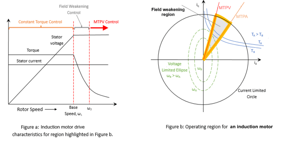
The preceding image is for illustration purposes only and is not to scale.
Traditionally, to generate optimal reference current data you required an actual motor and hardware in a dyno setup. However, using an actual induction motor and hardware to design a motor and the control algorithm can be impractical because of higher operation costs and time, safety issues, and sporadic machine and inverter failures. This example solves these problems by using a simulation-based model driven by a LUT that contains motor parameter data generated using data obtained from Motor-CAD™. It uses LUTs that contain d-axis and q-axis flux linkages, slip table, and torque data parameterized over and .
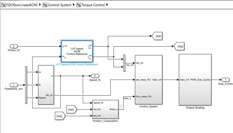
The example uses the LUT based ACIM Control Reference block that uses the induction motor d-axis and q-axis flux linkages, torque, and slip data to design and implement flux-weakening torque control using the optimal reference current and LUTs created using iterative analytical methods.
By default, this example uses the pregenerated and LUTs of optimal reference currents generated using the motor characterization data generated from Motor-CAD™ derived data. However, as an alternative, you can provide the LUT based ACIM Control Reference block with the flux linkage tables of the nonlinear induction motor to generate reference current and LUTs, and use them in the same example.
Using LUT-based motor data in place of hardware testing simplifies control algorithm design as follows:
Simulation-based validation — Run the LUT-based induction motor model in simulation to validate machine and control algorithm behavior under challenging operating conditions. This eliminates the need for a physical dyno setup and reduces development time.
High-fidelity motor representation — The example uses precalibrated LUTs generated by solving nonapproximated nonlinear motor equations offline. Because the LUT data captures the actual nonlinear motor characteristics, the control algorithms run on controller hardware with high efficiency and accuracy. For a customized nonlinear induction motor, the example also supports providing flux linkage tables as inputs to the LUT based ACIM Control Reference block.
Reduced real-time computational load — Instead of solving computationally intensive nonlinear motor equations in real time on the controller, the algorithm reads precomputed LUT values. This avoids the approximations and complexity that real-time solvers require for nonlinear induction motors. For any operating point defined by speed and torque, the LUT based ACIM Control Reference block interpolates among its nearest neighboring points from the internally computed (or user provided) and LUTs to give the optimal reference currents for the operating point.
Field-weakening with MTPA — Build a control algorithm that compensates for the reduced torque caused by magnetic saturation of the induction motor stator core. The LUT data accounts for nonlinear flux linkage behavior, enabling accurate field-weakening operation across the full speed range.
Model
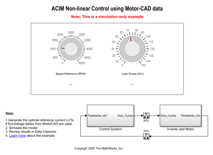
This example includes the FOCNonLinearACIM.slx Simulink® model.
You can use this model only for simulation.
About Model Data
By default, the example uses the LUT data file ACIMidiqLUT and the Motor-CAD™ data file IMFluxMotorCADData. The model initialization script FOCofNonLinearACIMdata.m loads and preprocesses these files.
The file ACIMidiqLUT.mat contains precomputed reference‑current lookup tables for FOC of nonlinear ACIM. The LUT based ACIM Control Reference block uses this data to generate the stator d-axis and q-axis current references.
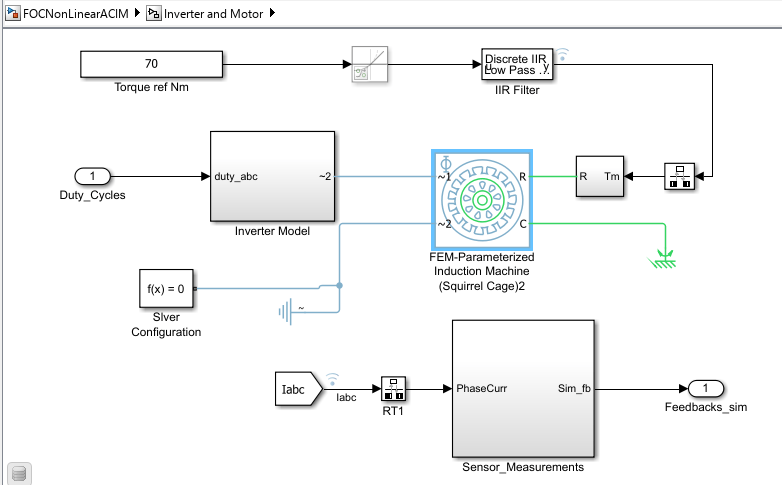
The FEM-Parameterized Induction Machine (Squirrel Cage) (Simscape Electrical) block is parameterized using the Motor-CAD™ flux linkage and slip table data. For more information, see Import Induction Machine (Squirrel Cage) Flux Linkage Data from Motor-CAD (Simscape Electrical).
Simulate Model
1. Open the Simulink model FOCNonLinearACIM.
2. Click Run on the Simulation tab to simulate the model.
3. Set the reference speed and load torque values using the Speed Reference (RPM) and Load Torque (Nm) knobs.
4. Click Data Inspector on the Simulation tab to view and analyze the simulation results.
See Also
LUT based ACIM Control Reference

