Main Content

estimatePLLPhaseNoise

R2026b

Estimate phase noise contributions of each building blocks of PLL

Since R2026b

Description

out = estimatePLLPhaseNoise(Block=gcb) returns the estimated phase noise for the currently selected PLL reference architecture block from Mixed-Signal Blockset™.

The function reads the parameters from the PLL block to build a phase-domain model. It then computes the phase noise contribution from each building block of the PLL including the VCO, reference, divider, charge pump, and loop filter resistors and capacitors, sums them in the linear power domain, converts the results to phase noise in dBc/Hz, and then plots the results against the offset frequency.

Note

You need a license to Control System Toolbox™ to use this functionality.

out = estimatePLLPhaseNoise(Block,Name=Value) uses the specified Name-Value pair arguments to override the block parameters to estimate PLL phase noise.

[out,config] = estimatePLLPhaseNoise(Block,Name=Value) returns the PLL configuration and the estimated PLL phase noise.

out = estimatePLLPhaseNoise('',Architecture=Architecture,ReferenceFrequency=ReferenceFrequency,ChargePumpCurrent=ChargePumpCurrent,VCOSensitivity=VCOSensitivity,Name=Value) estimates the PLL phase noise directly from MATLAB® command window using the specified Name-Value arguments without using any Simulink® block. You must specify the reference architecture, reference frequency, charge pump current, and VCO sensitivity.

Examples

collapse all

Open the model simplePLL attached to this example as a supporting file. The model consists of an Integer N PLL with Single Modulus Prescaler block and a PLL Testbench block.

open_system('simplePLL.slx')
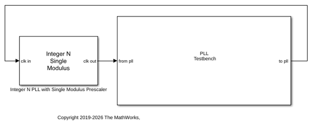
Double-click the Integer N PLL with Single Modulus Prescaler block to open the Block Parameters dialog box and verify these settings:

  • Check that the impairments are disabled in the PFD and Charge pump tabs.

  • In the Charge pump tab, the Output current is set to 2.7 mA. The Deadband compensation and Input threshold parameters are kept at default values.

  • In the VCO tab, the VCO sensitivity is set to 20 MHz/V. The free running frequency is set to 2.78 GHz, which is slightly lower than the target lock frequency. The phase noise frequency offset vector is set to [100e3 1e6 3e6 10e6] Hz. The phase noise level corresponding to these frequency offsets are set to [-108 -134 -145 -154] dBc/Hz.

  • Considering the reference input frequency to the PLL is 1.6 MHz, the Clock divider value and the Min clock divider value in the Prescaler tab is set to $\frac{2.8\textrm{e9}}{1.6\textrm{e6}}=1750$.

  • In the Loop Filter tab, the Loop bandwidth is set to 160 kHz, 1/10th of the reference input frequency. The phase margin is kept at default 45 degrees. Filter component values are calculated automatically.

Estimate the phase noise contribution of individual building blocks.

out = estimatePLLPhaseNoise(Block='simplePLL/Integer N PLL with Single Modulus Prescaler')
--- PLL Phase Noise Contribution Summary ---
  [not plotted] Reference - ReferencePhaseNoise not provided
  [not plotted] Divider - DividerPhaseNoise not provided and UseDSMDividerNoise is false
  [not plotted] PFD/CP - ChargePumpNoiseDensity is zero
  [not plotted] R4 thermal - R4 is zero (not present)
  [dominant] VCO - 100.0% of total integrated phase noise power
--------------------------------------------


out = 

  struct with fields:

               FrequencyOffset: [502×1 double]
               TotalPhaseNoise: [502×1 double]
                 VCOPhaseNoise: [502×1 double]
           ReferencePhaseNoise: [502×1 double]
             DividerPhaseNoise: [502×1 double]
          ChargePumpPhaseNoise: [502×1 double]
                  R2PhaseNoise: [502×1 double]
                  R3PhaseNoise: [502×1 double]
                  R4PhaseNoise: [502×1 double]
                  OpenLoopGain: [1×1 tf]
         ErrorTransferFunction: [1×1 tf]
    ClosedLoopTransferFunction: [1×1 tf]
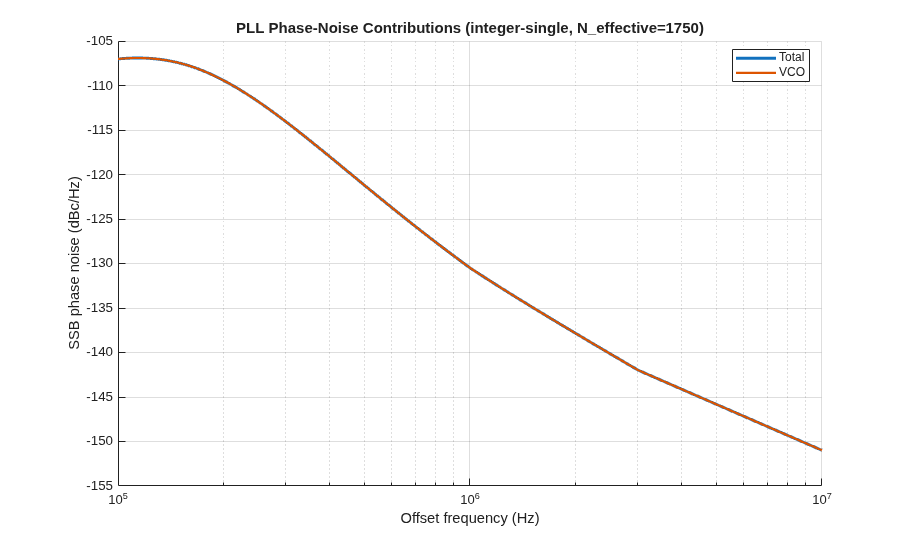
As you can see in this case, the only phase noise contribution is coming from the VCO.

Define the parameters for the PLL.

arch="integer-single";        % PLL architecture
RF=10e6;                      % Reference frequency
Icp=1e-3;                     % Charge pump current
Kvco=100e6;                   % VCO sensitivity
Rd=200;                       % Divider ratio
CP_nf=0.0015;                 % Transistor-level noise factor
CP_fc=100e3;                   % Charge pump flicker corner
R_fc=50e3;                    % Resistor flicker corner
VCO_pn=struct('f_Hz',[1e4 1e5 1e6 1e7], ...
              'L_dBc_per_Hz',[-77 -108 -134 -154]);    % VCO phase noise
Target_pn=struct('f_Hz',[1e4 1e5 1e6 1e7], ...
    'L_dBc_per_Hz',[-70 -100 -125 -145]);              % Target phase noise

Estimate the phase noise contributions of individual components of the PLL.

out = estimatePLLPhaseNoise( ...
    Architecture=arch, ...
    ReferenceFrequency=RF, ...
    ChargePumpCurrent=Icp, ...
    VCOSensitivity=Kvco, ...
    DividerRatio=Rd, ...
    CPNoiseFactor=CP_nf, ...
    ChargePumpFlickerCorner=CP_fc, ...
    ResistorFlickerCorner=R_fc, ...
    R2=1330, C1=1.31e-11, C2=1.44e-10, ...
    R3=17000, C3=9.41e-13, ...
    VCOPhaseNoise=VCO_pn, ...
    TargetPhaseNoise=Target_pn)
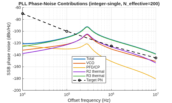
Figure contains an axes object. The axes object with title PLL Phase-Noise Contributions (integer-single, N_effective= 200 ), xlabel Offset frequency (Hz), ylabel SSB phase noise (dBc/Hz) contains 6 objects of type line. These objects represent Total, VCO, PFD/CP, R2 thermal, R3 thermal, Target PN.

--- PLL Phase Noise Contribution Summary ---
  [not plotted] Reference - ReferencePhaseNoise not provided
  [not plotted] Divider - DividerPhaseNoise not provided and UseDSMDividerNoise is false
  [not plotted] R4 thermal - R4 is zero (not present)
  [dominant] R3 thermal - 89.5% of total integrated phase noise power
--------------------------------------------
out = struct with fields:
               FrequencyOffset: [502×1 double]
               TotalPhaseNoise: [502×1 double]
                 VCOPhaseNoise: [502×1 double]
           ReferencePhaseNoise: [502×1 double]
             DividerPhaseNoise: [502×1 double]
          ChargePumpPhaseNoise: [502×1 double]
                  R2PhaseNoise: [502×1 double]
                  R3PhaseNoise: [502×1 double]
                  R4PhaseNoise: [502×1 double]
                  OpenLoopGain: [1×1 tf]
         ErrorTransferFunction: [1×1 tf]
    ClosedLoopTransferFunction: [1×1 tf]
         TargetFrequencyOffset: [4×1 double]
         TargetPhaseNoiseLevel: [4×1 double]
                   TargetDelta: [4×1 double]

Name-Value Arguments

collapse all

Specify optional pairs of arguments as Name1=Value1,...,NameN=ValueN, where Name is the argument name and Value is the corresponding value. Name-value arguments must appear after other arguments, but the order of the pairs does not matter.

Example: out = estimatePLLPhaseNoise(Block,DSMOrder=2) estimates the phase noise for the specified Block but overrides the order of the Fractional N DSM to 2.

Path to a Mixed-Signal Blockset PLL architecture block, specified as a string scalar or character vector. If you do not specify a block name and a Simulink model is open, the function uses the currently selected block.

To compute phase noise from MATLAB command window without a Simulink model, you can use an empty string ''.

PLL architecture type as defined by the PLL reference architecture block from Mixed-Signal Blockset, specified as:

  • "integer-single" — Integer N PLL with Single Modulus Prescaler

  • "integer-dual" — Integer N PLL with Dual Modulus Prescaler

  • "frac-accum" — Fractional N PLL with Accumulator

  • "frac-dsm" — Fractional N PLL with Delta Sigma Modulator

Note

If you do not specify a block, the function requires you to provide this argument.

Reference input clock frequency, specified as a scalar in Hz.

Note

If you do not specify a block, the function requires you to provide this argument.

Charge pump output current, specified as a scalar in Amperes.

Note

If you do not specify a block, the function requires you to provide this argument.

VCO sensitivity, specified as a scalar in Hz/V. It is the measure of change in output frequency for input voltage change.

If you are estimating phase noise components for a PLL block, the function reads the maximum VCO sensitivity from the block. For VCOs specified via a frequency-voltage lookup table, this represents the worst-case (steepest) slope of the tuning characteristic.

Note

If you do not specify a block, the function requires you to provide this argument.

Value by which the single modulus prescaler divides the input frequency, specified as a scalar.

Dependencies

The function uses this argument when the Architecture is set to "integer-single".

Value of the prescaler divider inside the dual modulus prescaler, specified as a scalar. The function uses this argument to calculate the effective divider value.

Dependencies

The function uses this argument when the Architecture is set to "integer-dual".

Value of the program counter inside the dual modulus prescaler, specified as a scalar. The function uses this argument to calculate the effective divider value.

Dependencies

The function uses this argument when the Architecture is set to "integer-dual".

Value of the swallow counter inside the dual modulus prescaler, specified as a scalar. The function uses this argument to calculate the effective divider value.

Dependencies

The function uses this argument when the Architecture is set to "integer-dual".

Value by which the fractional clock divider divides the input frequency, specified as a scalar.

Dependencies

The function uses this argument when the Architecture is set to "frac-accum" or "frac-dsm".

Value of the loop filter resistor 2, specified as a scalar in ohms.

Value of the loop filter resistor 3, specified as a scalar in ohms.

Value of the loop filter resistor 4, specified as a scalar in ohms.

Value of the loop filter capacitor 1, specified as a scalar in farads.

Value of the loop filter capacitor 2, specified as a scalar in farads.

Value of the loop filter capacitor 3, specified as a scalar in farads.

Value of the loop filter capacitor 4, specified as a scalar in farads.

Phase noise of the free-running VCO, specified as a structure. The structure contains the following fields:

Field NameDescription
f_HzFrequency offsets of the phase noise from the carrier frequency, specified as a real valued vector in Hz.
L_dBc_per_HzThe phase noise power in a 1 Hz bandwidth centered at the specified frequency offsets relative to the carrier, specified as a real valued vector in dBc/Hz.

Phase noise of the reference oscillator, specified as a structure. The structure contains the following fields:

Field NameDescription
f_HzFrequency offsets of the phase noise from the carrier frequency, specified as a real valued vector in Hz.
L_dBc_per_HzThe phase noise power in a 1 Hz bandwidth centered at the specified frequency offsets relative to the carrier, specified as a real valued vector in dBc/Hz.

Phase noise generated from the divider, specified as a structure. The structure contains the following fields:

Field NameDescription
f_HzFrequency offsets of the phase noise from the carrier frequency, specified as a real valued vector in Hz.
L_dBc_per_HzThe phase noise power in a 1 Hz bandwidth centered at the specified frequency offsets relative to the carrier, specified as a real valued vector in dBc/Hz.

Note

If you provide the value for DividerPhaseNoise, the function uses the value directly ignoring the setting of the UseDSMDividerNoise argument.

Enable analytical delta-sigma modulator quantization noise modeling for fractional-N PLLs, specified as true or false.

Dependencies

To enable the analytical DSM modeling, you must not provide the value for DividerPhaseNoise argument.

Delta-sigma modulator order, specified as an integer in the range [1,4].

Fractional part of the fractional divider ratio, specified as a scalar.

White current noise density of the charge pump, specified as a scalar in A2/Hz.

If you do not provide a value for ChargePumpNoiseDensity, the function calculates the white current noise density from the equation 4*kB*Temperature*CPNoiseFactor*ChargePumpCurrent.

1/f corner frequency for the charge pump noise, specified as a scalar in Hz.

Charge pump noise scaling factor, specified as a scalar.

If you do not provide a value for ChargePumpNoiseDensity, the function calculates the white current noise density from the equation 4*kB*Temperature*CPNoiseFactor*ChargePumpCurrent.

Common 1/f corner frequency for all loop filter resistors, specified as a scalar in Hz.

Offset frequencies to evaluate phase noise, specified as a vector in Hz.

If you specify the frequency offset points, the function automatically merges the specified offsets with the noise mask frequency points for accurate interpolation. The 500-point log-spaced frequency offset grid includes the specified frequency offset points.

Operating temperature, specified as a real scalar in ℃. Operating temperature determines the level of thermal (Johnson) noise.

Option to enable loop filter impairments (thermal noise), specified as true or false.

Target phase noise, specified as a structure. The structure contains the following fields:

Field NameDescription
f_HzFrequency offsets of the phase noise from the carrier frequency, specified as a real valued vector in Hz.
L_dBc_per_HzThe phase noise power in a 1 Hz bandwidth centered at the specified frequency offsets relative to the carrier, specified as a real valued vector in dBc/Hz.

Output Arguments

collapse all

Phase noise analysis results, returned as a structure. The results contain the frequency offsets, total phase noise, per-source phase noise components, open loop gain, and sensitivity and complementary sensitivity functions.

FieldSizeDescription
FrequencyOffsetN-by-1

Frequency offset vector in Hz.

TotalPhaseNoiseN-by-1

Total output single-side-band (SSB) phase noise in dBc/Hz.

VCOPhaseNoiseN-by-1

Phase noise contribution from VCO in dBc/Hz.

ReferencePhaseNoiseN-by-1

Phase noise contribution from reference oscillator in dBc/Hz.

DividerPhaseNoiseN-by-1

Phase noise contribution from divider or DSM in dBc/Hz.

ChargePumpPhaseNoiseN-by-1

Phase noise contribution from charge pump in dBc/Hz.

R2PhaseNoiseN-by-1

Thermal noise contribution from resistor R2 in dBc/Hz.

R3PhaseNoiseN-by-1

Thermal noise contribution from resistor R3 in dBc/Hz.

R4PhaseNoiseN-by-1

Thermal noise contribution from resistor R4 in dBc/Hz.

OpenLoopGaintransfer function

Open-loop transfer function, defined as: Ls=Icp·Kvco·ZLFN·s.

ErrorTransferFunctiontransfer function

Error transfer function, also known as sensitivity function,defined as: 11+L.

This shapes the VCO phase noise. The shaping is high-pass.

ClosedLoopTransferFunctiontransfer function

Closed-loop transfer function, also known as complementary sensitivity, defined as: L1+L.

This shapes the reference and divider phase noise. The shaping is low-pass.

TargetFrequencyOffsetM-by-1

Target phase noise frequency offset points.

TargetPhaseNoiseLevelM-by-1

Phase noise power at target frequency offset points.

TargetDeltaM-by-1

Difference between target and estimated phase noise level. A +dB value indicates the estimated phase noise is above the target phase noise level.

Effective PLL configuration, returned as a structure. The structure contains the final PLL configuration used for analysis after merging the block parameters and name-value argument overrides.

More About

collapse all

Tips

  • If you are using a PLL block in a Simulink model, you can override any block parameter by specifying the corresponding name-value argument. For example, estimatePLLPhaseNoise(Block=gcb, ChargePumpCurrent=2e-3) uses the loop filter and VCO settings from the block but overrides the charge pump current to 2 mA. This allows you to quickly estimate the effect of certain parameters without changing the model.

  • You can use the returned transfer function objects further analyses, such as checking the gain and phase margins (margin(out.OpenLoopGain)), verifying loop bandwidth (bandwidth(out.ClosedLoopTransferFunction)), and visualizing VCO noise shaping (bode(out.ErrorTransferFunction)).

  • For quick sanity checks, verify that the loop bandwidth matches your design specifications and that the phase margin is above 45°.

Version History

Introduced in R2026b