Wideband Transmit Array
Wideband transmit array
Libraries:
Phased Array System Toolbox /
Transmitters and Receivers
Description
The Wideband Transmit Array block transmits wideband plane waves from the elements of a sensor array. The block divides the transmitted signals into subbands and then applies a phase shift for each subband according to the radiating direction. The resulting subband signals are then combined to form the output.
Ports
Input
Output
Parameters
To edit block parameters interactively, use the Property Inspector. From the Simulink® Toolstrip, on the Simulation tab, in the Prepare gallery, select Property Inspector.
Main Tab
Select this parameter to indicate that the input signal is demodulated at a carrier frequency.
Data Types: Boolean
Modulated signal carrier frequency, specified as a positive scalar. Units are in Hz.
Dependencies
To enable this parameter, set the Assume modulated input check box.
Data Types: double
Specify sensor gain measure as dB or
dBi.
When you set this parameter to
dB, the input signal power is scaled by the sensor power pattern (in dB) at the corresponding direction and then combined.When you set this parameter to
dBi, the input signal power is scaled by the directivity pattern (in dBi) at the corresponding direction and then combined. This option is useful when you want to compare results with the values computed by the radar equation that uses dBi to specify the antenna gain. The computation using thedBioption is expensive as it requires an integration over all directions to compute the total radiated power of the sensor. The default value isdB.
Select this check box to specify array weights using the input port
W. The input port appears only when this box is checked.
Sensor Array Tab
Element Parameters
Dependencies
To enable this parameter, set Element type to Cardioid Antenna.
Coordinate system of custom antenna pattern, specified
az-el or phi-theta. When you
specify az-el, use the Azimuth angles
(deg) and Elevations angles (deg) parameters to
specify the coordinates of the pattern points. When you specify
phi-theta, use the Phi angles (deg)
and Theta angles (deg) parameters to specify the coordinates of the
pattern points.
Dependencies
To enable this parameter, set Element type to
Custom Antenna.
Phi angles of points at which to specify the antenna radiation pattern, specify as a real-valued 1-by-P row vector. P must be greater than 2. Angle units are in degrees. Phi angles must lie between 0° and 360° and be in strictly increasing order.
Dependencies
To enable this parameter, set the Element type parameter to
Custom Antenna and the Coordinate system of custom
antenna pattern parameter to
phi-theta.
Theta angles of points at which to specify the antenna radiation pattern, specify as a real-valued 1-by-Q row vector. Q must be greater than 2. Angle units are in degrees. Theta angles must lie between 0° and 360° and be in strictly increasing order.
Dependencies
To enable this parameter, set the Element type parameter to
Custom Antenna and the Coordinate system of custom
antenna pattern parameter to
phi-theta.
Align directions of the element normals to the direction of the array normal.
Dependencies
This parameter is enabled when Element type is set to
Custom Antenna.
Beamwidth of antenna pattern, specified as a 1-by-2 real-valued vector.
Dependencies
This parameter is enabled when Element type is set to
Gaussian Antenna.
Array Parameters
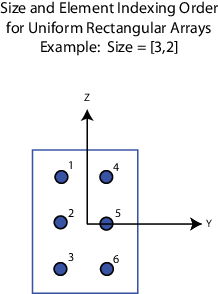
Dimensions of a URA array, specified as a positive integer or 1-by-2 vector of positive integers.
If Array size is a 1-by-2 vector, the vector has the form
[NumberOfArrayRows,NumberOfArrayColumns].If Array size is an integer, the array has the same number of rows and columns.
When you set Specify sensor array as to
Replicated
                subarray
, this parameter applies to each subarray.
For a URA, array elements are indexed from top to bottom along the
leftmost column, and then continue to the next columns from left to right. In this
figure, the Array size value of [3,2] creates an
array having three rows and two columns.
Dependencies
To enable this parameter, set Geometry to
URA.
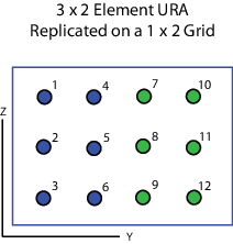
Rectangular subarray grid size, specified as a single positive integer, or a 1-by-2 row vector of positive integers.
If Grid size is an integer scalar, the array has
an equal number of subarrays in each row and column. If
Grid size is a 1-by-2 vector of
the form [NumberOfRows, NumberOfColumns], the
first entry is the number of subarrays along each column. The
second entry is the number of subarrays in each row. A row is
along the local y-axis, and a column is along
the local z-axis. The figure here shows how
you can replicate a 3-by-2 URA subarray using a Grid
size of [1,2].
Dependencies
To enable this parameter, set Sensor
array to Replicated
subarray and Subarrays
layout to
Rectangular.
Version History
Introduced in R2015b