Flow Resistance (G)
General resistance in a gas branch

Libraries:
Simscape /
Foundation Library /
Gas /
Elements
Description
The Flow Resistance (G) block models a general pressure drop in a gas network branch. The pressure drop is proportional to the square of the mass flow rate and to the density of the gas. The constant of proportionality is determined from a nominal operating condition specified in the block dialog box.
Use this block when the only data available for a component is its pressure drop as a function of its mass flow rate. Combine the block with others to create a custom component that more accurately captures the pressure drop that it induces—for example, a heat exchanger based on a chamber block.
Mass Balance
The volume of gas inside the flow resistance is assumed to be negligible. The mass flow rate in through one port must then exactly equal the mass flow rate out through the other port:
where and are defined as the mass flow rates into the component through ports A and B, respectively.
Energy Balance
Energy can enter and leave the flow resistance through the gas conserving ports only. No heat exchange occurs between the wall and the environment. In addition, no work is done on or by the fluid. The energy flow rate in through one port must then exactly equal the energy flow rate out through the other port:
where ϕA and ϕB are the energy flow rates into the flow resistance through ports A and B.
Momentum Balance
The relevant external forces on the fluid include those due to pressure at the ports and those due to viscous friction at the component walls. Gravity is ignored as are other body forces. Expressing the frictional forces in terms of a loss factor ξ yields the semi-empirical expression:
where:
Δp is the pressure drop from port A to port B—that is, pA + pB.
ξ is the loss factor.
ρ is the fluid density.
S is the flow area.
The pressure drop equation is implemented with two modifications. First, to allow for a change in sign upon reversal of flow direction, it is rewritten:
where the pressure drop is positive only if the mass flow rate is too. Second, to eliminate singularities due to flow reversal—which can pose a challenge for numerical solvers during simulation—it is linearized in a small region of near-zero flow:
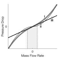
where is a threshold mass flow rate below which the pressure drop is linearized. The figure shows the modified pressure drop against the local mass flow rate (curve I):
Above , the pressure drop approximates that expressed in the original equation (curve II) and it varies with . This dependence is commensurate with that observed in turbulent flows.
Below , the pressure drop approximates a straight line with slope partly dependent on (curve III) and it varies with . This dependence is commensurate with that observed in laminar flows.
For ease of modeling, the loss factor ξ is not required as a block parameter. Instead, it is automatically computed from the nominal condition specified in the block dialog box:
where the asterisk (*) denotes a value at the nominal operating condition. Underlying all of these calculations is the assumption that the threshold mass flow rate is much smaller than the nominal value . Replacing the fraction ξ/(2S2) in the expression for the pressure drop yields:
or, equivalently:
where C is a constant of proportionality between the pressure drop across the flow resistance and the local mass flow rate. It is defined as:
If the fluid density is assumed to be invariant, then its nominal and actual
values must always be equal. This is the case whenever the nominal value is
specified in the block dialog box as 0—a special value used to
signal to the block that the fluid density is a constant. The ratio of the two is
then 1 and the fraction C/ρ reduces to:
Ports
Conserving
Parameters
Extended Capabilities
Version History
Introduced in R2017b