Generated Code Structure for Reusable Subsystems
This topic assumes that you have generated Structured Text code from a Simulink® model. If you have not yet done so, see Generate Structured Text from the Model Window.
The example in this topic shows generated code for the CODESYS Version 2.3 IDE. Generated code for other IDE platforms looks different.
Open the
plcdemo_reusable_subsystemmodel. To open the model, enter:openExample('plcdemo_reusable_subsystem');Open the PLC Coder app.
Click Generate PLC Code.
The Simulink PLC Coder™ software generates Structured Text code and places it in
current_folder/plcsrc/plcdemo_reusable_subsystem.expIf you do not have the
plcdemo_reusable_subsystem.expfile open, open it in the MATLAB® editor.The following figure illustrates the mapping of the generated code to Structured Text components for a reusable Simulink subsystem. This graphic contains a copy of the hierarchical subsystem, ReusableSubsystem. This subsystem contains two identical subsystems, S1 and S2. This configuration enables code reuse between the two instances (look for the
ReusableSubsystemstring in the code).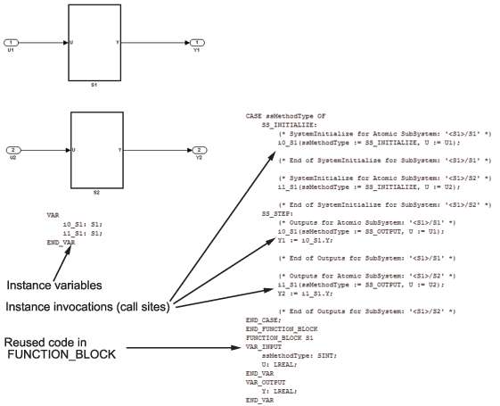
Examine the generated Structured Text code. The code defines
FUNCTION_BLOCK S1once.Look for two instance variables that correspond to the two instances declared inside the parent
FUNCTION_BLOCK ReusableSubsystem(i0_S1: S1andi1_S1: S1). The code invokes these two instances separately by passing in different inputs. The code invokes the outputs per the Simulink execution semantics.For IEC 61131-3 compatible targets, the non-step and the output
ssMethodTypedo not use the output variables of theFUNCTION_BLOCK. Therefore, the generated Structured Text code forSS_INITIALIZEdoes not contain assignment statements for the outputsY1andY2.Note
This optimization is applicable only to IEC 61131-3 compatible targets.