Model and Analyze Microstrip Diplexer using Open Loop Resonator
This example shows how to model and analyze a microstrip diplexer with the open loop resonator using RF PCB Toolbox.
The diplexer represents the simplest form of a multiplexer. It allows a simultaneous transmission and reception of signals by using a single antenna. Diplexers are the key components in microwave communication systems, such as radar systems, cellular phones, and satellite communication systems to reduce the size and the mass of the whole device.
This example models and analyzes a microstrip diplexer using two band-pass filters for the Industrial Scientific Medical (ISM) applications at 5.8 GHz and the WIMAX applications at 3.17 GHz to 4.2 GHz bands, along with a matching network by using open loop resonators and with the good arrangement of the transmission feed lines.
The Section 1 shows the analysis of open loop bandpass filters at 3.28 GHz and 5.8 GHz respectively and the section 2 describes the microstrip diplexer and scattering parameter behavior with the designed dimensions used [1].
Create and Analyze Open Loop Bandpass Filters
This section will show the analysis of open loop bandpass filters designed at 5.8 GHz and 3.28 GHz with the designed dimensions in [1].
The schematic of the open loop resonator is show below:
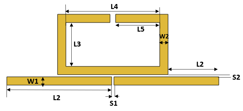
Create the variable for the substrate
% Dimensions of the substrate
h = 1.6e-3;      % Height of the substrate
er = 4.4;        % Dielectric constant
tand = 0.025;    % Loss tangent
Create Bandpass Filter at 5.86 GHz
Create the variable to set the dimensions in [1] of the open loop filter that is designed at 5.8 GHz.
W1_f1 = 0.75e-3; W2_f1 = 0.75e-3; S1_f1 = 0.2e-3; S2_f1 = 0.2e-3;
L1_f1 = 7.6e-3;  L3_f1 = 1.35e-3;  L4_f1 = 6.2e-3; S3_f1 = 0.7e-3;
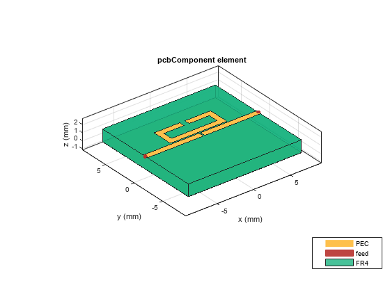
Pass the variables with the dimensions at 5.8 Ghz to the function CreateOpenLoopFilter and visualize it.
[OpenLoop_Filter1, pcb_fiter1] = CreateOpenLoopFilter(W1_f1,W2_f1,S1_f1,S2_f1,L1_f1,L3_f1,L4_f1,S3_f1,h,er,tand);
figure; show(pcb_fiter1);
Analyze the behaviour of open loop filter at 5.86 GHz using sparameters.
spar_filter1 = sparameters(pcb_fiter1,linspace(4.5e9,7e9,51));
figure; rfplot(spar_filter1,1,1);
hold on;  rfplot(spar_filter1,2,1);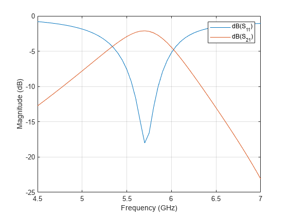
Create Bandpass Filter at 3.28 GHz
Create the variable to set the dimensions in [1] of the open loop filter that is designed at 3.28 GHz.
W1_f2 = 0.75e-3; W2_f2 = 0.75e-3; S1_f2 = 0.2e-3; S2_f2 = 0.2e-3;
L1_f2 = 8.5e-3;  L3_f2 = 1.3e-3; L4_f2 = 12.5e-3; S3_f2 = 0.5e-3;
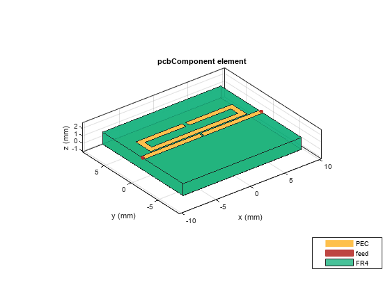
Pass the variables with the dimensions at 3.28 GHz to the function CreateOpenLoopFilter and visualize it.
[OpenLoop_Filter2, pcb_fiter2] = CreateOpenLoopFilter(W1_f2,W2_f2,S1_f2,S2_f2,L1_f2,L3_f2,L4_f2,S3_f2,h,er,tand);
figure; show(pcb_fiter2);
Analyze the behavior of open loop filter at 3.28 GHz using sparameters.
spar_filter2 = sparameters(pcb_fiter2,linspace(2.5e9,4.5e9,51));
figure; rfplot(spar_filter2,1,1);
hold on;  rfplot(spar_filter2,2,1);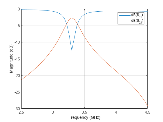
Create and Analyze Microstrip Diplexer Using Open Loop Bandpass Filter
Model the microstrip diplexer using the open loop filters designed in section 1 with the proper arrangement of filter along with transmission feed lines.
shapeFilter1 = copy(OpenLoop_Filter1);
shapeFilter2 = copy(pcb_fiter2.Layers{1});
shapeFilter2 = rotateZ(shapeFilter2,90);
shapeFilter2 = rotateZ(shapeFilter2,180);
L1_filter2   = 8.5e-3;
L1 = L1_f1;
W1 = W1_f1;
S1 = S1_f1;
trnsfac = -(L1+L1+S1)/2;
shapeFilter2 = translate(shapeFilter2,[trnsfac+W1/2,L1_filter2-W1/4,0]);

Lport3 = 5e-3;
t = 1.5e-3;
port3 = traceRectangular("Length",W1,"Width",Lport3,"Center",[-t,-Lport3/2]);

diplexer = shapeFilter1+shapeFilter2+port3;

pcb_diplexer = pcbComponent;
h = 1.6e-3;      % Height of the substrate
er = 4.4;        % Dielectric constant
tand = 0.025;    % Loss tangent
gndL1 = 21e-3;
gndW1 = 25e-3;
gndL = L1_f1+L1_f1+S1_f1; % GroundPlaneLength
pcb_diplexer.BoardThickness = h;

gnd = traceRectangular("Length",gndL1,"Width",gndW1,"Center",[0,6e-3]);
sub = dielectric("Name",{'FR4'},"EpsilonR",er,"LossTangent",tand,"Thickness",h);
pcb_diplexer.BoardShape = gnd;
pcb_diplexer.Layers = {diplexer,sub,gnd};
pcb_diplexer.FeedDiameter = W1/2;
pcb_diplexer.FeedLocations = [-t,-Lport3,3,1;-gndL/2+W1/2,2*L1_filter2-W1/4,3,1;gndL/2,0,3,1];

figure; show(pcb_diplexer);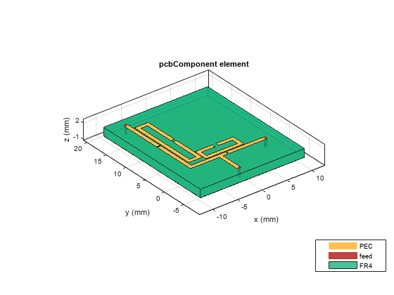
Analyze the sparameters of diplexer
spar = sparameters(pcb_diplexer,[linspace(2e9,4e9,51),linspace(4.01e9,8e9,51)]);
figure; rfplot(spar,1,1);
hold on; rfplot(spar,1,2);
hold on; rfplot(spar,1,3);
hold on; rfplot(spar,2,3);
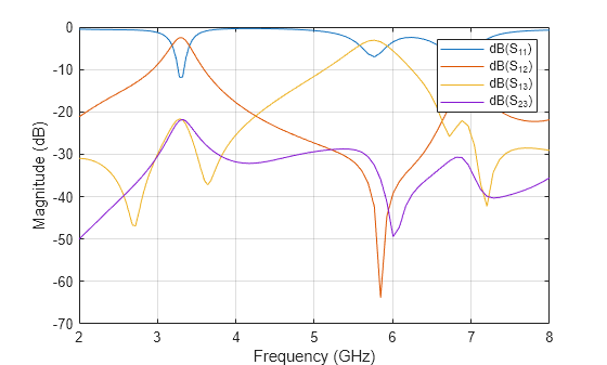
The simulated insertion loss is about 2.38 dB for the Rx filter and 0.9 dB for the Tx filter. The return loss in the upper and lower filter is about 16.47 dB and 15.89 dB, respectively. The isolation between the two channels is greater than 25 dB. Several transmissions zeros near the pass bands located at 2.72 GHz, 3.68 GHz, 5.96 GHz and 7.28 GHz respectively are obtained.
CreateOpenLoopFilter is the function that creates open loop filter shape and the pcbComponent with different dimensions.
function [OpenLoopShape, OpenLoopPcbComp] = CreateOpenLoopFilter(W1,W2,S1,S2,L1,L3,L4,S3,h,er,tand)
rec1 = traceRectangular("Length",L4,"Width",L3,"Center",[0,W1/2+S2+W2+L3/2]);
rec2 = traceRectangular("Length",L4+(2*W2),"Width",L3+(2*W2),"Center",[0,W1/2+S2+(L3+(2*W2))/2]);
split1 = traceRectangular("Length",S3,"Width",W2+0.01*L3,"Center",[0,W1/2+S2+W2+L3+W2/2]);
openLoop1 = (rec2-rec1)-split1;

% input/output line
mline = traceRectangular("Length",L1+L1+S1,"Width",W1,"Center",[0,0]);
FeedSplit = traceRectangular("Length",S1,"Width",W1,"Center",[0,0]);
feed = mline-FeedSplit;
OpenLoopShape = openLoop1+feed;

% Create the variables to define the substrate dimensions

gndL = L1+L1+S1; % GroundPlaneLength
gndW = 15e-3;    % GroundPlaneWidth

pcb = pcbComponent;
pcb.BoardThickness = h;
gnd = traceRectangular("Length",gndL,"Width",gndW,"Center",[0,0]);
sub = dielectric("Name",{'FR4'},"EpsilonR",er,"LossTangent",tand,"Thickness",h);
pcb.BoardShape = gnd;
pcb.Layers = {OpenLoopShape,sub,gnd};
pcb.FeedDiameter = W1/2;
pcb.FeedLocations = [-gndL/2,0,1,3;gndL/2,0,1,3;];
OpenLoopPcbComp = pcb;
end
Reference
[1]. A. Chinig, A. Errkik, L .El Abdellaoui, A. Tajmouati "Design of a Microstrip Diplexer and Triplexer Using Open Loop Resonators," Journal of Microwaves, Optoelectronics and Electromagnetic Applications, Vol. 15, No. 2, June 2016.