Create Traffic Signals at Junctions
This example shows how to create working traffic signals at a junction using a four-way protected left traffic pattern. To add traffic signals in RoadRunner, you use the Signal Tool, which lets you configure junction signalization and control traffic signal phases. This example shows the entire workflow for creating a junction, adding dynamic signalization to the junction, adding props or assemblies to the signal junction, and modifying signal phases and maneuvers.
Create New Scene
Create a new scene within a project.
Open RoadRunner, and from the start page, click New Scene.
On the Select a Project window, select the project that you want to work in.
The RoadRunner canvas opens, where you can start building your scene.
Create Junctions
To place traffic signals in your scene, first create a junction. You can use the Road Plan Tool to create automatic junctions at road intersections.
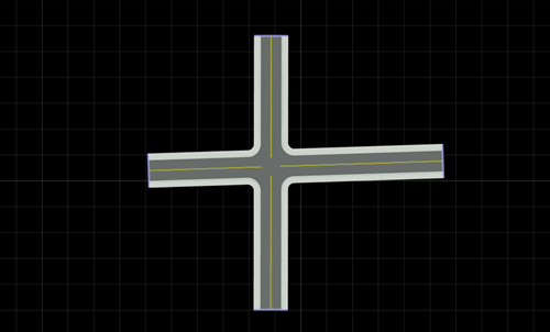
To create a four-way intersection, create two roads that fully overlap:
Click the Road Plan Tool
 .
.Right-click at a start location and an end location to create a road segment.
Create another road segment that overlaps the previously created road. This action creates a four-way junction.
To create custom junctions manually, you can use the Custom Junction Tool.
Add Signals to Junctions
To configure junction signalization and signal traffic phases, use the Signal Tool
![]() .
.
The Signal Tool provides several autosignalization operations for automatically applying predefined signalization templates to a junction. The junction signalization can be static (not changing, for example, controlled by stop signs) or, as in the case of this example, dynamic (controlled by traffic signals).
The autosignalization operations can also automatically place Prop Assembly Assets and Signal Assets which will automatically link to the corresponding signals. You can also use predefined prop assembly to the link the props to the corresponding signals.
To add a predefined prop assembly asset to the scene, select the prop in the Library Browser.
Navigate to the
Assetsfolder, and selectAssemblies. For this example, select the ProtectedLeft1 prop.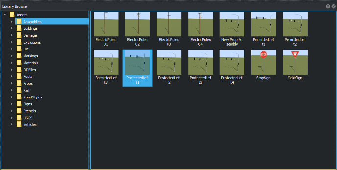
To add signalization, click Signal Tool and select the junction.
To signalize the junction, click Auto Signalize in the Attributes pane.
From the Auto Signalize Junction dialog box, select a signalization template and click Signalize. For this example, select the four-way Protected Left template. Select Automatically Place Selected Prop to add the props and link it to the signal.
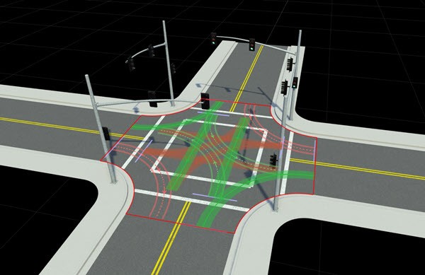
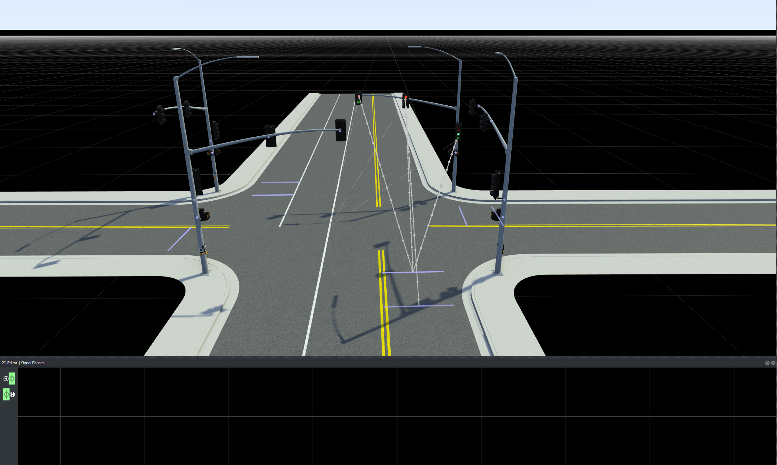
The scene shows the autosignalized junction with a four-way protected left traffic pattern. When you add prop or signal assemblies to the scene, they are automatically linked to the junction.
Inspect Phases and Maneuver Roads
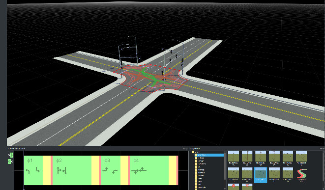
You can now inspect and edit maneuver roads, signal phases, and intervals using the Signal Phase Editor in the 2D Editor pane.
A phase indicates which signals are active and the state of the maneuver roads, for example, whether traffic may enter the junction along a given maneuver road.
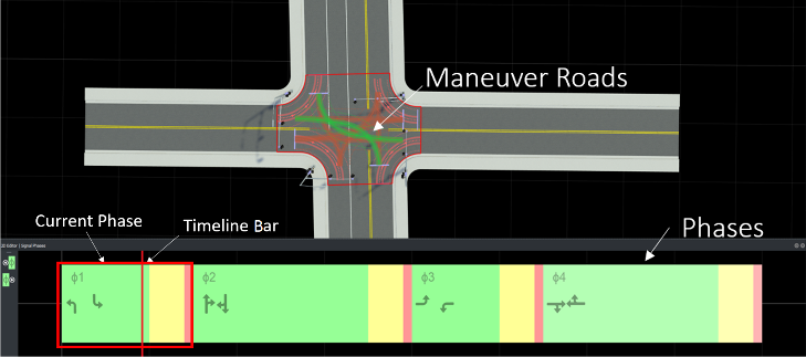
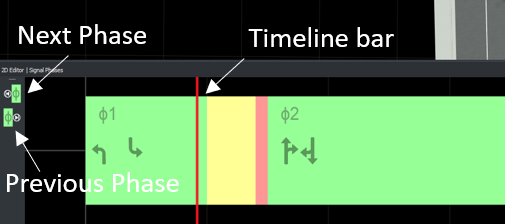
This example shows four phases with three Red-Yellow-Green intervals per phase. An interval is a period in a junction that corresponds to allowed movements. You can drag the timeline bar across phases and observe the maneuver roads changing.
The highlighted (green) maneuver roads in the scene correspond to the first phase (highlighted by a red box) in the Signal Phase Editor. The phase also shows the road maneuver direction symbols. That is, the highlighted green maneuver road matches the road symbol in the current phase.
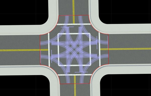
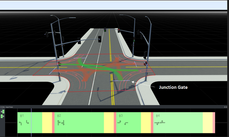
The phases, maneuver roads, and signal assets are automatically linked to the junctions. The gray dotted line shows road gates that link the signal to its corresponding junction.
Click the purple junction gate to view its corresponding signal.
Use the timeline bar to navigate across phases and observe the signal lights changing color with each interval.
Edit Signal Phases
You can add, remove, or navigate between signal phases using the Signal Phase Editor in the 2D Editor pane.
Add and Delete Signal Phases
To add a signal phase to your scene:
Click the Signal Tool and select the junction you want to signalize.
Right-click in the 2D Editor pane to create a phase. You can also right-click beyond the end of the phases to create additional empty phases.
To duplicate a phase, right-click on the existing phase.
To delete a phase, select individual phases in the 2D Editor pane and press the Delete key. To delete all the phases, select the junction and press the Delete key or select Edit > Delete.
Navigate Between Signal Phases
In the 2D Editor pane, you can either left-click the phase, use Next Phase and Previous Phase on the left, or drag the timeline bar across the phases to preview the phases and the corresponding maneuver roads.
See Also
Topics
- Signal Tool
- Custom Junction Tool
- Create Simple RoadRunner Scene
- Create Roads Around Imported GIS Assets