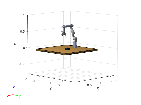
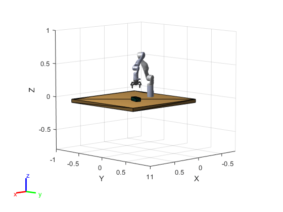
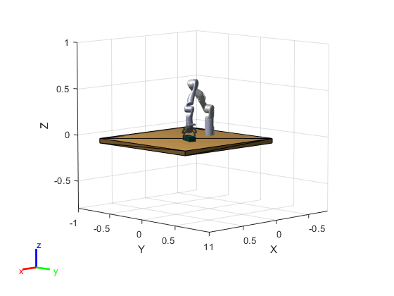
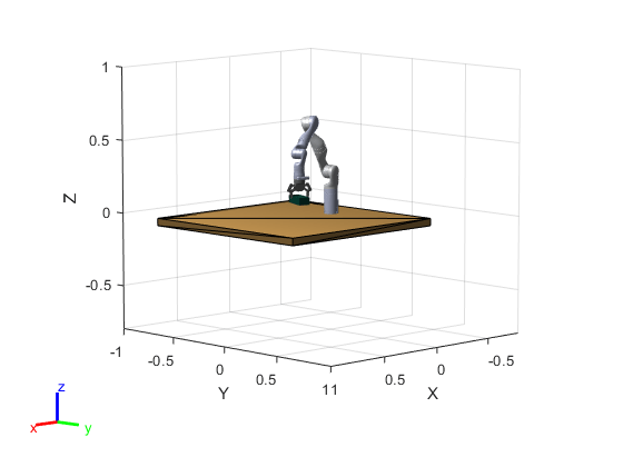
Simulate a Detect and Pick Algorithm Using OpenCV Interface and Rigid Body Tree Robot Model
This example shows how to simulate an end-to-end rigid body tree workflow for a KINOVA® Gen3 robot to detect a rectangular object using OpenCV Interface, and then pick and move the object with inverse kinematics.
This example uses the algorithm created using Computer Vision Toolbox™ Interface for OpenCV in MATLAB to detect the object from the image (either simulated image or a captured image), and calculates the position and orientation data. Robotics System Toolbox™ is used to model, simulate, plan motion, and visualize the manipulator.
Note: Execute the script section-by-section as mentioned in this example. Do not skip any section as each section contains some dependency on reference variables.
Required Products
MATLAB®
Robotics System Toolbox™
Robotics System Toolbox™ Support Package for Manipulators
Computer Vision Toolbox™ (required only if you want to use the
detectObjectOCVMEX function for object detection, provided with this example)Image Processing Toolbox™ (required as a dependency of Computer Vision Toolbox)
Computer Vision Toolbox Interface for OpenCV in MATLAB (required only if you want to modify the
detectObjectOCVMEX function, provided with this example)
Create a Rigid Body Tree Model and Define Initial Pose
Create a rigid body tree model for Kinova Gen3 robot, and define initial pose and get end effector transformation.
The initial pose is defined such that the focus of the wrist-mounted camera on Gen3 robot is exactly downwards, and the camera axis is perpendicular to the surface of the bench (to be created in the next step) in the downward direction.
% Load the robot model from a .mat file as a rigidBodyTree object
load('exampleHelperKINOVAGen3GripperCollManip.mat');
gen3 = robot;
gen3.DataFormat = 'column';

% Define initial pose by specifying the joint values (in radians) at ['Shoulder_Link', 'HalfArm1_Link',	'HalfArm2_Link', 'ForeArm_Link', 'Wrist1_Link',	'Wrist2_Link','Bracelet_Link']
q_home = [0 0.35 pi -1.20 0 -pi/2 pi/2]';

% Get the end effector transform
endEffectorTransf  = getTransform(gen3,q_home,'EndEffector_Link');
Create Simulation Environment with a Bench and a Box
Create a simulation environment with a bench (to which the base of manipulator is fixed) and a box placed on the bench.
To create the collision geometry for both objects for visualization, you can use collisionBox function. To add desired pose for the collision geometry, use the homogeneous transformation matrix.
Note: The object must be placed within the field of view limit of the camera for successful object detection. For a given camera scan position, the camera field of view limits are [0.365, 0.635] and [-0.239, 0.243] respectively for the X and Y axis. The object height must be within the appropriate limit ([0.03 0.1]) as per the gripper geometry.
% Create bench mesh (X_length, Y_length, Z_length)
bench = collisionBox(1.3, 1.3, 0.05);

% Compute Homogeneous transformation matrix using translation vector at [x y z] position of the bench
TBench = trvec2tform([0.35 0 -0.025]);
bench.Pose = TBench;

% Height of the box in meter.
boxHeight = 0.05;
% Position of the box in the base reference system [x y z]
boxPosition = [0.45 0.15 boxHeight/2]';
% Orientation of the box in degrees
boxOrientation = -20;
% Box mesh (X_length, Y_length, Z_length)
box = collisionBox(0.075, 0.17, boxHeight);
Rz = [cosd(boxOrientation) -sind(boxOrientation) 0; sind(boxOrientation) cosd(boxOrientation) 0; 0 0 1];

% Create 3x3 rotation matrix
transf = rotm2tform(Rz);
% Homogeneous transformation(4x4) for the box
transf(:,4) = [boxPosition; 1];
box.Pose = transf;
% Creating a Box structure to be used in the next section to find pose transformation for visualization of the box object with the gripper
Box.mesh = box;

% Create environment array of all collision objects
environmentWorld = {bench, box};
Visualize Robot in Scan Position with the Simulation Environment
Visualize the robot model and the environment objects. Set the color of the bench and the box objects.
% Close the previous simulation figure window if it is present while running this script again
close(findobj('type','figure','name','Simulation of Gen3 to Detect and Pick Object'))

% Current figure handle
hFig = figure('name', 'Simulation of Gen3 to Detect and Pick Object');
% Current axes handle
ax = gca;

show(gen3,q_home,'PreservePlot',false,'FastUpdate',true,'Frames',"off");
set(gcf,'Visible','on');
hold on

% Initialize array for graphics objects
patchObj = gobjects(1,2);
for i = 1:2
    [~,patchObj(i)] = show(environmentWorld{i});
end
patchObj(1).FaceColor = [0.89 0.68 0.37];
patchObj(2).FaceColor = [0.04 0.321 0.262];
axis([-0.8 1 -1 1 -0.8 1])
set(ax,'units','inch')
set(gca,'position',[0.5 0 5 5])

Find Camera Transformation with Reference to the Base of Kinova Gen3 Robot
In Kinova Gen3 robot, the camera is located at 0.041m (offset) in y-direction in the local frame of the end effector.
% Camera offset in positive y-direction
cameraOffset = 0.041;
% Compute the actual camera transform
actualCameraTransf = endEffectorTransf * trvec2tform([0,cameraOffset,0]);
% Absolute depth from the base of the robot
cameraZ = actualCameraTransf(3,4);
% Subtract the height of the object (depth from the surface of an object with reference to the origin)
zDistance = cameraZ - boxHeight ;
However, if your robot is situated at some height from the reference plane, then consider that value in the zDistance parameter.
Note: If you are using a different object instead of the one provided in this simulation, update the boxHeight parameter accordingly. This value is used to calculate the location of the object in subsequent sections.
Define Camera Parameters
Note: The parameters defined here are based on the vision module provided by Kinova for the Gen3 robot. If you are using any other camera module, update the camera parameters accordingly.
% Horizontal fov (field of view) in radians
cameraParams.hfov = 1.211269;
% Vertical fov in radians
cameraParams.vfov = 0.7428;
Acquire the Image for Object Detection
Select the type of image, which is the input for the OpenCV object detection function.
Select Simulated Image for using the simulated image, or select Camera Image if you want to use an actual image captured by the vision module camera for the simulation purpose.
To use Kinova vision module to capture actual image for the simulation, you need to complete the steps 1 and 2 explained in Configure MATLAB to Acquire Images from Vision Module.
% Define the Kinova Gen3 robot IP using the "gen3KinovaIP" variable. gen3KinovaIP = '192.168.1.10'; selectImageType ="Simulated"; rgbImg = exampleHelperAcquireImage(environmentWorld,actualCameraTransf,selectImageType,cameraParams,gen3KinovaIP);
Note: If you want to use an existing image saved on your computer, then load the image (using imread function) in the "rgbImg" variable after running this section. Also, update the camera parameters accordingly and select the image type as Simulated Image in the drop-down menu, so that you can proceed without hardware connection.
Use OpenCV Object Detection Algorithm and Compute Object Location in a Global or Base Frame of Kinova Gen3 Robot
Select Use detectObjectOCV MEX Function from the below drop-down menu to use the MEX function generated from the OpenCV file (detectObjectOCV.cpp) to detect the rectangular object and extract the position and orientation parameters in terms of pixel and degrees, respectively.
Note: To use detectObjectOCV MEX Function, Computer Vision Toolbox is a required product. Please ensure that this toolbox is installed in your system. To check the list of installed products, use "ver" command in the MATLAB command window.
If Computer Vision Toolbox is not installed in your system, then select Skip Object Detection to skip the OpenCV object detection to avoid the issues related to MEX files dependency.
selectObjectDetectionWorkflow =
"OpenCVWorkflowEnabled"
selectObjectDetectionWorkflow = "OpenCVWorkflowEnabled"
The overall algorithm to detect an object's position and orientation is similar to the one explained in Detect Position and Orientation of a Rectangular Object Using OpenCV.
Note: If you are using an actual image from the vision module or a captured custom image for the simulation, then you may need to change the threshold parameters of the OpenCV object detection logic. Use the below command in the MATLAB command window to open the detectObjectOCV.cpp file to make the necessary changes.
>> open detectObjectOCV.cpp
If you have made changes in the OpenCV source file (detectObjectOCV.cpp), then follow these steps to generate an updated MEX file that reflects the changes (for more information regarding these steps, see Computer Vision Toolbox™ Interface for OpenCV in MATLAB):
Install
Computer Vision Toolbox Interface for OpenCV in MATLAB.Select a compiler version using this command:
>> mex -setup
Create the MEX-file from the source file:
>> mexOpenCV detectObjectOCV.cpp
The below section of code calculates the absolute position of the object in a global frame of reference.
if (strcmp(selectObjectDetectionWorkflow,"OpenCVWorkflowEnabled"))
    % Add path to the MEX function location and use it to compute the
    % location and orientation of the object
    dirPath = codertarget.robotmanipulator.internal.getSpPkgRootDir;
    dirFullPath = fullfile(dirPath,'resources','opencv_mex');
    addpath(dirFullPath);
    result = detectObjectOCV(rgbImg);

    % Convert the result into double data type for further calculations
    result = double(result);

    % Calculating horizontal and vertical focal length
    hfocalLength = (size(rgbImg,2)/2)/tan(cameraParams.hfov/2); %horizontal focal length
    vfocalLength = (size(rgbImg,1)/2)/tan(cameraParams.vfov/2); %vertical focal length

    % Computed center point of the box object
    centerBoxwrtCenterPixel = [round(size(rgbImg,1)/2)-result(1), round(size(rgbImg,2)/2)-result(2)];
    worldCenterBoxwrtCenterPixel(1) = (zDistance/vfocalLength)*centerBoxwrtCenterPixel(1); % in meters
    worldCenterBoxwrtCenterPixel(2) = (zDistance/hfocalLength)*centerBoxwrtCenterPixel(2);
    actualpartXY = actualCameraTransf(1:2,4)' + worldCenterBoxwrtCenterPixel;
    boxCenterPoint = [actualpartXY(1), actualpartXY(2), boxHeight/2];
else
    % Skipping the OpenCV MEX function and taking the predefined
    % object location and orientation for the further computation
    result = [boxPosition(1), boxPosition(2), boxOrientation];
    boxCenterPoint = boxPosition';
end
Note: if you are using the actual image of a different object, change the boxHeight parameter accordingly in the "boxCenterPoint" definition.
Update Simulation Environment Based on the Computed Object Location
Update the simulation environment to display the object in the simulation world as per the input image and the computed object location.
% Update box location and orientation in simulation figure window
% Position of the box in the base reference system [x y z]
boxPosition = [boxCenterPoint(1) boxCenterPoint(2) boxHeight/2]';
% Orientation of the box in degrees
boxOrientation = result(3);
Rz = [cosd(boxOrientation) -sind(boxOrientation) 0; sind(boxOrientation) cosd(boxOrientation) 0; 0 0 1];
% Create 3x3 rotation matrix
transf = rotm2tform(Rz);

% Homogeneous transformation(4x4) for the box
transf(:,4) = [boxPosition; 1];
% Updating pose
box.Pose = transf;

% Note: If you want to update the object dimension as per the actual
% object, then update it here by changing box.X, box.Y, box.Z parameter
% values.

% Delete previous box patch object
delete(patchObj(2));

% Create new patch object with updated box parameters
[~,patchObj(2)] = show(box);
patchObj(2).FaceColor = [0.04 0.321 0.262];

Motion Planning to Pick and Move the Object with Inverse Kinematics
This step involves the following tasks:
Task-1: Reach 15cm above the object
Task-2: Reach near to the object and grab it in the gripper
Task-3: After picking the object, reach 15cm above the surface of the bench
% Define the sample time and trajectory time array (For simulation
% purpose, we are using the same trajectory time for all the three tasks)

waypointTimes = [0;4];
% Sample time
ts = 0.2;
% Creating a trajectory time array
trajTimes = waypointTimes(1):ts:waypointTimes(end);
Task-1: Reach 15cm above the object
In this task, compute the waypoints, orientations and the initial guess for inverse kinematics.
pickedPartTransf = getTransform(gen3,q_home,'pickedPart');
% Define reach to height (+Z direction) for Task-1 and Task-3
reachToHeight = 0.15;
% Configure the waypoint to reach 0.15m above the object for the first task
goalPointForTask1 = boxCenterPoint' + [0;0;reachToHeight];
waypointForTask1 = horzcat([pickedPartTransf(1,4); pickedPartTransf(2,4); pickedPartTransf(3,4)], ...
    goalPointForTask1);

% Orientation at grasp pose
orientationAtGraspPose = result(3);
orientations = [-pi/2 pi 0; wrapToPi(deg2rad(orientationAtGraspPose)) pi 0]';

ikInitGuess = q_home';
Generate a trajectory for the Task-1 using above parameters.
computedTrajForTask1 = exampleHelperGenerateTrajectory(gen3,waypointForTask1,orientations,trajTimes,waypointTimes,ikInitGuess);
Visualize the trajectory for Task-1
disp('---* Reaching 15cm above to the object*---');---* Reaching 15cm above to the object*---
r = rateControl(1/ts);
for idx = 1:numel(trajTimes)
    config = computedTrajForTask1.position(:,idx)';
    show(gen3,config','PreservePlot',false,'FastUpdate',true,'Frames',"off");
    waitfor(r);
end

Task-2: Reach near to the object and grab it in the gripper
Compute waypoints, orientations and initial guess for inverse kinematics,.
pickedPartTransf = getTransform(gen3,config','pickedPart');
waypointForTask2 = horzcat([pickedPartTransf(1,4); pickedPartTransf(2,4); pickedPartTransf(3,4)], boxCenterPoint' );
orientations = [deg2rad(orientationAtGraspPose) pi 0; deg2rad(orientationAtGraspPose) pi 0]';
ikInitGuess = config;
Generate a trajectory for the Task-2 using above parameters
computedTrajForTask2 = exampleHelperGenerateTrajectory(gen3,waypointForTask2,orientations,trajTimes,waypointTimes,ikInitGuess);
Visualize the trajectory for Task-2
disp('---* Reaching near to the object*---');---* Reaching near to the object*---
r = rateControl(1/ts);
for idx = 1:numel(trajTimes)
    config = computedTrajForTask2.position(:,idx)';
    show(gen3,config','PreservePlot',false,'FastUpdate',true,'Frames',"off");
    waitfor(r);
end
Attach the object to the robot's gripper to grab it.
% Temporary pose for creating plot handle for the object
tempPose = [0,0,0];
correctPose = Box.mesh.Pose;
Box.mesh.Pose = trvec2tform(tempPose);
[~, Box.plot] = show(Box.mesh);
Box.plot.LineStyle = 'none';
Box.plotHandle = hgtransform;

% Attach the plot handle to the parent
Box.plot.Parent = Box.plotHandle;
Box.mesh.Pose = correctPose;
Box.plotHandle.Matrix = Box.mesh.Pose;
Box.plot.FaceColor = [0.04 0.321 0.262];

partBody = getBody(gen3,'pickedPart');
addCollision(partBody,"box", [Box.mesh.X, Box.mesh.Y, Box.mesh.Z]);

CurrentRobotJConfig = config';
% Compute current transformation matrix for pickedPart for setting up the pose of the object mesh
CurrentRobotTaskConfig = getTransform(gen3,CurrentRobotJConfig,'pickedPart');
patchObj(2).Visible = 'off';
show(gen3,CurrentRobotJConfig,'PreservePlot',false,'FastUpdate',true,'Frames',"off");
Box.mesh.Pose = CurrentRobotTaskConfig ;
Box.plotHandle.Matrix = Box.mesh.Pose;

disp('---*Object is attached to the robot gripper*---');---*Object is attached to the robot gripper*---
Task-3: Reach to 15cm above the surface of the bench after grabbing the object
Compute waypoints, orientations and the initial guess for inverse kinematics for Task-3.
pickedPartTransf = getTransform(gen3,config','pickedPart');
goalPointForTask3 = [pickedPartTransf(1,4);pickedPartTransf(2,4);reachToHeight];
waypointForTask3 = horzcat([pickedPartTransf(1,4); pickedPartTransf(2,4); pickedPartTransf(3,4)], goalPointForTask3);

orientations = [deg2rad(orientationAtGraspPose) pi 0; deg2rad(orientationAtGraspPose) pi 0]';
Generate a trajectory for Task-3 using above parameters.
ikInitGuess = config;
computedTrajForTask_3 = exampleHelperGenerateTrajectory(gen3,waypointForTask3,orientations,trajTimes,waypointTimes,ikInitGuess);
Visualize the trajectory for Task-3.
disp('---*Reaching 15cm above the object after grabbing it in gripper*---');---*Reaching 15cm above the object after grabing it in gripper*---
r = rateControl(1/ts);
for idx = 1:numel(trajTimes)
    config = computedTrajForTask_3.position(:,idx)';
    show(gen3,config','PreservePlot',false,'FastUpdate',true,'Frames',"off");
    CurrentRobotTaskConfig = getTransform(gen3,config','pickedPart'); %Computing current transformation matrix for picked part body for setting up the pose of the object mesh
    Box.mesh.Pose = CurrentRobotTaskConfig;
    Box.plotHandle.Matrix = Box.mesh.Pose;
    waitfor(r);
end

disp('--*All simulation tasks of picking and moving the object are completed*--');--*All simulation tasks of picking and moving the object are completed*--
Clear variables, which are not significant, from Workspace.
clear partBody patchObj Bench CurrentRobotTaskConfig robot transf vfocalLength hfocalLength orientations ...
    orientationAtGraspPose i idx Rz tempPose TBench worldCenterBoxwrtCenterPixel actualpartXY ...
    reachToHeight r ikInitGuess pickedPartTransf config correctPose CurrentRobotJConfig ans ax bench box Box Bench ...
    cameraZ environmentWorld goalPointForTask1 goalPointForTask3 actualCameraTransf boxHeight boxPosition boxOrientation ...
    endEffectorTransf centerBoxwrtCenterPixel zDistance boxCopy dirPath path