Sign-Following Robot with ROS 2 in MATLAB
This example shows you how to use MATLAB® to control a simulated robot running on a external ROS-based simulator over ROS 2 network. It then captures how to generate a ROS 2 node for the control algorithm and deploy it to a remote device. The example shown here uses ROS 2 and MATLAB for simulation, and MATLAB Coder™ for code generation and deployment.
In this example, you run a MATLAB script that implements a sign-following algorithm and controls the simulated robot to follow a path based on signs in the environment. The algorithm receives the location information and camera information from the simulated robot, which is running in a separate ROS-based simulator. The algorithm detects the color of the sign and sends the velocity commands to turn the robot based on the color detected. In this example, the algorithm is designed to turn left when the robot encounters a blue sign and turn right when the robot encounters a green sign. Finally, the robot stops when it encounters a red sign.
To see this example using ROS 1 or Simulink®, see Sign Following Robot with ROS in MATLAB.
Prerequisites
To run this example, you are required to set up Docker® in your host environment (Windows Subsystem for Linux (WSL), Linux® or Mac) and create a Docker image for Gazebo. For more information on how to configure Docker, see Install and Set Up Docker for ROS, ROS 2, and Gazebo.
Start Docker Container
With the prerequisites set up and the Docker image created, the first step is to launch an instance of Docker container.
To start a Docker container, run the following command in WSL/Linux/Mac terminal:
$ docker run -it --net=host -v /dev/shm:/dev/shm --name ros2_sign_follower <image-name>
Here, 'ros2_sign_follower' is the name of the Docker container. Replace the <image-name> with the name of the Docker image created in the prerequisite section.
Get IP Address of Docker Container
While the Docker container is running, obtain the IP address of the Docker container running on the remote device. This IP address is necessary for establishing an SSH connection and accessing the Gazebo simulator. Note that the IP address of the Docker container is the same as the IP of the host machine.
To retrieve this IP address, run the following command in the WSL/Linux/Mac terminal:
$ ifconfig

The connection type can vary depending on how you are connected to the host. In this case use the Ethernet (eth0), however, in many cases the wireless (wlan0) is the appropriate connection.
Start Gazebo Robot Simulator
Once the container is running, start the Gazebo robot simulator inside the Docker container.
Open a terminal within the Docker container by executing the following command in the WSL/Linux/Mac terminal:
$ docker exec -it ros2_sign_follower /bin/bash
Here, 'ros2_sign_follower' is the name of Docker container.
In the Docker container terminal, launch the TurtleBot in a Gazebo world by running the following command:
$ source start-gazebo-maze-world.sh
To view the Gazebo world, open a web browser on your host machine and connect to the URL <docker-ip-address>:8080. If Docker is running on your host machine, you can simply use localhost:8080. You can now visualize and interact with the Gazebo world directly in your web browser.

Configure MATLAB for ROS 2 Network
Launch MATLAB on your host machine and set the ROS_DOMAIN_ID environment variable to 25 and configure the ROS Middleware in MATLAB to rmw_fastrtps_cpp to match the robot simulator's ROS settings. For detailed steps, refer to Switching Between ROS Middleware Implementations.
Once the domain ID is set, run the following command in MATLAB to verify that the topics from the robot simulator are visible:
setenv('ROS_DOMAIN_ID','25')
ros2('topic','list')
Note: If you are unable to view topic published by Gazebo (/camera/image_raw), or facing frequent message drop, run the following command in MATLAB Command Window: "setenv('FASTRTPS_DEFAULT_PROFILES_FILE', <path-to-fastdds-xml-file>)". Replace <path-to-fastdds-xml-file> with the path of 'fastdds.xml' provided with the example.
Establish Communication with Gazebo over ROS 2 Network
Create a ROS 2 node using the specified domain ID.
domainID = 25;
n = ros2node("matlab_example_robot",domainID);
Create publishers and subscribers to relay messages to and from the robot simulator over the ROS 2 network. Update the Quality of Service (QoS) policies of publisher and subscriber. You need subscribers for the image and odometry data. To control the robot, set up a publisher to send velocity commands using the /cmd_vel topic.
imgSub = ros2subscriber(n, "/camera/image_raw","sensor_msgs/Image","Reliability","besteffort","Durability","volatile","Depth",5);

odomSub = ros2subscriber(n, "/odom","nav_msgs/Odometry","Reliability","besteffort","Durability","volatile","Depth",5);

[velPub, velMsg] = ros2publisher(n, "/cmd_vel", "geometry_msgs/Twist","Reliability","reliable","Durability","volatile","Depth",5);
Define the image processing color threshold parameters. Each row defines the threshold values for the different colors.
colorThresholds = [100 255 0 55 0 50; ... % Red
                   0 50 50 255 0 50; ...  % Green
                   0 40 0 55 50 255]';    % Blue
Create Sign Following Controller Using Stateflow Chart
This example provides an example helper MATLAB Stateflow® chart that takes in the image size, coordinates from processed image, and the robot odometry poses. The chart provides linear and angular velocity to drive the robot based on these inputs.
controller = ExampleHelperSignFollowingControllerChart;
open('ExampleHelperSignFollowingControllerChart');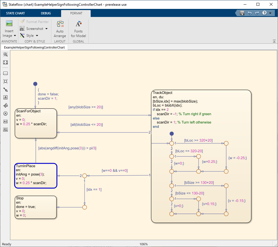
Run Control Loop
This section runs the controller to receive images and move the robot to follow the sign. The controller does the following steps:
Gets the latest image and odometry message from the ROS network.
Runs the algorithm for detecting image features (
ExampleHelperSignFollowingProcessImg).Generates control commands from the Stateflow chart using
step.Publishes the velocity control commands to the ROS network.
To visualize the masked image the robot sees, change the value of doVisualization variable to true.
ExampleHelperSignFollowingSetupPreferences;

% Control the visualization of the mask
doVisualization = false;

r = rateControl(10);
receive(imgSub); % Wait to receive an image message before starting the loop
receive(odomSub);
while(~controller.done)
    % Get latest sensor messages and process them
    imgMsg = imgSub.LatestMessage;
    odomMsg = odomSub.LatestMessage;
    [img,pose] = ExampleHelperSignFollowingProcessMsg(imgMsg, odomMsg);

    % Run vision and control functions
    [mask,blobSize,blobX] = ExampleHelperSignFollowingProcessImg(img, colorThresholds);
    step(controller,'blobSize',blobSize,'blobX',blobX,'pose',pose);
    v = controller.v;
    w = controller.w;

    % Publish velocity commands
    velMsg.linear.x = v;
    velMsg.angular.z = w;
    send(velPub,velMsg);

    % Optionally visualize
    % NOTE: Visualizing data will slow down the execution loop.
    % If you have Computer Vision Toolbox, we recommend using
    % vision.DeployableVideoPlayer instead of imshow.
    if doVisualization
        imshow(mask);
        title(['Linear Vel: ' num2str(v) ' Angular Vel: ' num2str(w)]);
        drawnow('limitrate');
    end
    % Pace the execution loop.
    waitfor(r);
end
You should see the robot moving in the ROS-based robot simulator as shown below.

The robot follows the signs and stops at the final STOP sign. Close the Gazebo scene after simulation using CTRL+C on Docker terminal and relaunch Gazebo.
Generate and Deploy ROS 2 Node
After the controller is verified, the next step is to generate a ROS 2 node for the sign following robot algorithm using MATLAB Coder and deploy it on the remote machine (Docker container) running Gazebo. Deployment enables ROS nodes to run on the remote machines directly, resulting in faster executions. Create a MATLAB Coder configuration object that uses "Robot Operating System 2 (ROS 2)" hardware. For the Docker container for ROS Toolbox, set the following configuration parameters before remote deployment:
RemoteDeviceAddressis IP address of Docker container.RemoteDeviceUsernameis 'user'RemoteDevicePasswordis 'password'
Note that the actual values might be different for your remote device. Verify them before deployment. Set the build action to 'Build and Run' so that the deployed ROS node starts running after code generation.
cfg = coder.config("exe");
cfg.Hardware = coder.hardware("Robot Operating System 2 (ROS 2)");
cfg.Hardware.DeployTo = 'Remote Device';
cfg.Hardware.RemoteDeviceAddress = '192.168.192.129';
cfg.Hardware.RemoteDeviceUsername = 'user';
cfg.Hardware.RemoteDevicePassword = 'password';
cfg.Hardware.BuildAction = "Build and run";
Use DeploySignFollowingRobotROS2 function that contains the controller algorithm code verified in the previous section. Run the following command to generate the ROS node and deploy the controller. You should see the robot moving in the Gazebo world.
codegen DeploySignFollowingRobotROS2 -config cfg
The robot follows the signs and stops at the final STOP sign. Close the Gazebo scene after simulation using CTRL+C on Docker terminal.
Rerun Deployed Node
To rerun the deployed ROS node from MATLAB, create a ros2device object specifying the deviceAddress, username, and password values of the Docker container running Gazebo. This establishes an SSH connection between the ROS device and MATLAB. Check the available nodes on the connected remote device. Verify that the deployed ROS node, DeploySignFollowingRobotROS2, exists.
gazeboDevice = ros2device('192.168.192.129','user','password');
gazeboDevice.AvailableNodes
Run the ROS node deployed on the remote device using runNode function.
runNode(gazeboDevice,'DeploySignFollowingRobotROS2')