Read Accelerometer and Gyrometer Data from an STMicroelectronics Nucleo Board Using SCI Blocks
This example shows how to use Simulink® Coder™ Support Package to send data to your computer from a STMicroelectronics® Nucleo board and read it using serial (SCI) blocks.
This example has three models.
In the first model,
SCICommunication, the SCI Write block sends serial data to your computer. The SCI Read block reads the received data and displays it in Monitor and Tune.
In the second model,
AccelGyroSCI, the SCI Write block sends serial data to USBTX, the default serial transmit port on the Nucleo board. Unlike the first model, this model is deployed on the Nucleo board.
In the third model,
AccelGyroSCIHost, the Serial Read block from the Instrument Control Toolbox™ reads the data that is transmitted in the second model.
These models are pre-configured for STMicroelectronics Nucleo F401RE board. To configure these models for other supported Nucleo boards, browse to Simulation > Model Configuration Parameters > Hardware Implementation on the Simulink model toolbar. From the Hardware board list, select any other Nucleo board, and click OK.
Prerequisites
Before you start with this example, we recommend completing the Read Data from I2C-Based Sensors Using STMicroelectronics Nucleo Boards example.
Required Hardware
To run the models, you must have the following hardware:
Supported STMicroelectronics Nucleo board
USB cable
SparkFun 6 Degrees of Freedom IMU Digital Combo Board - ITG3200/ADXL345
Small breadboard (recommended) and breadboard wires
STMicroelectronics Nucleo SCI Communication Model
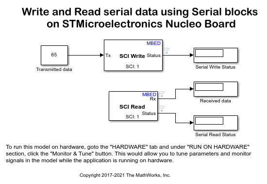
In this model, the SCI Write block sends serial data to your computer. The SCI Read block reads the received data and displays it in Monitor and Tune.
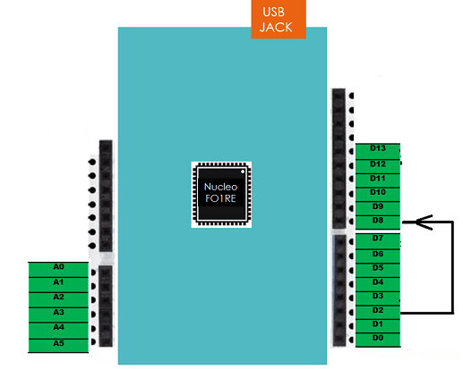
Connecting Pin D2 to Pin D8
Connect the D8 (serial Tx) pin to the D2 (serial Rx) pin using a breadboard wire. The model writes the serial data to the D8 pin. This data is looped back to the D2 pin on the Nucleo board.
You cannot use the D1 and D0 serial pins to send and receive data in Monitor and Tune. Monitor and Tune uses these pins when running the code on the model. Using the same pins to transmit data results in pin conflict.
Configuring SCI Write and SCI Read Blocks
This task explains how to configure the model to write and read serial data using the SCI Write and Read blocks.
1. Open the Read and write the serial data using SCI(serial) blocks on STMicroelectronics Nucleo board model.
2. In your Simulink model, double-click the SCI Write block, and do these steps:
a. Specify the SCI module parameter as 0.
b. Select the Output status option. When you select this option, the Status port becomes available.
This table lists the value at the Status port for different data transfer status.
    Output status(in decimal) |   Message
 _ _ _ _ _ _ _ _ _ _ _ _ _ _ _ _ _ _ _ _ _ _ _ _ _ _ _ _
      0                       |  Successful SCI operation
      1                       |  Receiver(Rx) busy
      2                       |  Transmitter(Tx) busy
      4                       |  SCI Parity error
      8                       |  SCI Frame error
     16                       |  SCI Bus error
     32                       |  SCI data not available
 _ _ _ _ _ _ _ _ _ _ _ _ _ _ _ _ _ _ _ _ _ _ _ _ _ _ _ _
3. Double-click the SCI Read block, and perform these steps:
a. Specify the SCI module parameter as 0.
b. Select the Output status option. When you select this option, the Status port becomes available.The value at the Status port for different data transfer status is same as listed in the previous table.
Configuring the Model for SCI
1. On the Simulink model toolbar, Open the Modeling tab and press CTRL+E to open Configuration Parameters dialog box.
2. Go to Hardware Implementation pane, select the STMicroelectronics Nucleo board that you are using from the Hardware board list. Do not change any other settings.
3. Browse to Hardware board settings > Target hardware resources > SCI1.
4. Set the Receive pin parameter to D2 and the Transmit pin parameter to D8. For more information on the serial pins available on your Nucleo board, refer to the datasheet of your board.
5. Click OK to save your changes.
Configure the Hardware and Model for Monitoring and Tuning
In this task, you will configure the hardware and tune parameters and monitor the serial data in the model while running the application on the Nucleo board.
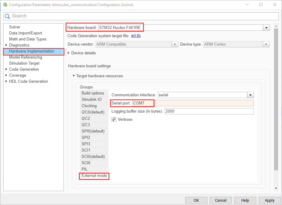
1. Open the Modeling tab and press Ctrl+E to open Configuration Parameters dialog box.

2. Navigate to Hardware Implementation > Target Hardware Resources > External Mode > COM Port and enter the COM port of the serial interface on Windows. To find the COM port on your Windows system, open the Device Manager window, and expand the Ports (COM & LPT) list. In the expanded list, locate STMicroelectronics STLink Virtual COM Port (COMx), where x is the number of the port.
3. Open the Hardware tab and click Monitor & Tune.

a. The Display block, Serial Write Status, displays the status as 0, indicating that the serial data write is successful.
b. The Display block, Serial Read Status, displays the status as 0, indicating that the serial data read is successful.
c. The Display block, Received data displays the data received by the SCI Read block. This value matches the data sent using the SCI Write block.
4. On the Hardware tab, click the Stop button to end the Monitor and Tune execution.
STMicroelectronics Nucleo AccelGyro SCI Model
In this model, the SCI Write block sends the Sparkfun Digital 6DOF accelerometer and gyrometer sensor data along the X, Y, and Z axes to USBTX, the default serial transmit port on the Nucleo board. Unlike the first model, this model is deployed on the Nucleo board.
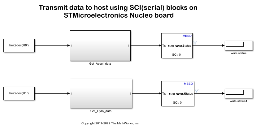
Configuring and Running the Model to Write Sensor Data
This task explains how to configure the model to write sensor data using the SCI Write block.
1. Connect the ITG3200/ADXL345 sensor to the STMicroelectronics Nucleo board as described in the Read data from an I2C based sensors using STMicroelectronics Nucleo board example.
2. Open the Read the Accelerometer and Gyrometer data and send it to host using SCI(serial) blocks on STMicroelectronics Nucleo board model.
3. On the Simulink toolbar, Open the Modeling tab and press CTRL+E to open Configuration Parameters dialog box.
4. In the Hardware Implementation pane, select the STMicroelectronics Nucleo board that you are using from the Hardware board list. Do not change any other settings.
5. Click OK
6. In your Simulink model, double-click the SCI Write block, and perform these steps.
a. Specify the SCI module parameter as 0.
b. Select the Output status option. When you select this option, the Status port becomes available.
This table lists the value at the Status port for different data transfer status.
    Output status(in decimal) |   Message
 _ _ _ _ _ _ _ _ _ _ _ _ _ _ _ _ _ _ _ _ _ _ _ _ _ _ _ _
      0                       |  Successful SCI operation
      1                       |  Receiver(Rx) busy
      2                       |  Transmitter(Tx) busy
      4                       |  SCI Parity error
      8                       |  SCI Frame error
     16                       |  SCI Bus error
     32                       |  SCI data not available
 _ _ _ _ _ _ _ _ _ _ _ _ _ _ _ _ _ _ _ _ _ _ _ _ _ _ _ _
7. On the Simulink model toolbar, click the Deploy To Hardware button. This action builds, downloads, and runs the model on the Nucleo board.
For more information, on how to configure I2C blocks in this model, see the Read data from an I2C based sensors using STMicroelectronics Nucleo board example.
Reading the Values Using Serial Terminal
You can read the values from the board using any serial terminal or by performing the steps specified in the third model. The advantage of using the serial terminal is that you can read the values without any need to install the Instrument Control Toolbox on your computer.
To read values using the serial terminal:
1. Open the serial terminal available in your computer. In this example, Putty is used.
2. In Putty, select Connection > Serial. Specify the COM port number of the serial interface on your Windows® system, and the baud rate of data transfer.
To find the COM port on your Windows system, open the Device Manager window, and expand the Ports (COM & LPT) list. In the expanded list, locate STMicroelectronics STLink Virtual COM Port (COMx), where x is the number of the port.
3. Click Open to see the serial data in the terminal.
4. Close the terminal to free the COM port after analyzing the data.
STMicroelectronics Nucleo AccelGyro SCI Host Model
In this model, the Serial Read block from the Instrument Control Toolbox reads the data that is transmitted in the second model. To use this model, you must have an Instrument Control Toolbox license.
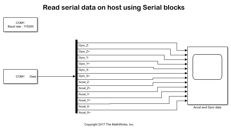
Configuring and Running the Model to Read Serial Data from the Sensor
Before opening the model, ensure that the Instrument Control Toolbox™ is installed in your computer. To check if the toolbox is available in your computer, use the ver command in the MATLAB® command window.
1. Open the Read the serial data using serial block on STMicroelectronics Nucleo board model.
2. Double-click the Serial Configuration block and set the Communication port parameter to the COM port number of the serial interface on your Windows system.
To find the COM port on your Windows system, open the Device Manager window, and expand the Ports (COM & LPT) list. In the expanded list, locate STMicroelectronics STLink Virtual COM Port (COMx), where x is the number of the port.
3. Double-click the Serial Receive block and set the Communication port and the Data size parameters.
4. On the Simulink model toolbar, set the Simulation mode to Normal, and click the Run button.
5. After the model is successfully built, double-click the Scope block Accel and Gyro data. Observe the accelerometer and gyrometer data for each axis separately.
Other Things to Try
Build and deploy the Read and write the serial data using SCI(serial) blocks on STMicroelectronics Nucleo board model with External mode on different pins using the SCI Write block.
Perform the steps in this example to communicate with other UART-based sensors.
Migrate to Embedded Coder® Support Package for STMicroelectronics® STM32 Processors
To migrate to the Embedded Coder® Support Package for STMicroelectronics® STM32 Processors, use:
Read Accelerometer and Gyrometer Data from an STMicroelectronics STM32F401RE Board Using USART Blocks (Embedded Coder) example to implement the equivalent STM32 processor support package.
Migrate SCI Block Usage to STM32 Processor Based Library Block (Embedded Coder) topic to migrate block usage.