V5 GPS Sensor
Add-On Required: This feature requires the Simulink Coder Support Package for VEX EDR V5 Robot Brain add-on.
Libraries:
Simulink Coder Support Package for VEX EDR V5 Robot Brain /
Sensors
Description
The GPS Sensor block reads position and orientation from the VEX V5 GPS Sensor connected to the robot.
The block outputs pose as a 3-by-1 vector representing X, Y coordinates and θ heading. Additionally, it outputs an estimate of position error.
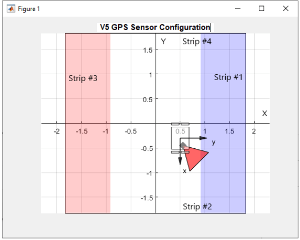
This block also allows you to visualize the sensor and robot configuration.
Ports
Output
Pose specified as a three-element vector of [x y
θ], where x and y corresponds to position and
θ corresponds to the orientation angle.
θ is positive clockwise and its range is
0-360 degrees.
Data Types: double
This port outputs the estimation of position error in meters.
Dependencies
Data Types: double
The Euler port outputs yaw, pitch, and roll angles as a 3-by-1 vector in the z-y-x sequence.
Dependencies
To enable this port select the Euler angles (deg) parameter.
Data Types: double
The Accel port outputs acceleration (or specific force) in x, y, and z order as a 3-by-1 vector. The Acceleration is measured in m/s2.
Dependencies
To enable this port select the Acceleration (m/s^2) parameter.
Data Types: double
The Ang rate port outputs the angle of rotation per second about the x-, y-, and z- axes of the sensor as a 3-by-1 vector. The angular rate is measured in deg/s.
Dependencies
To enable this port select the Angular rate (deg/s) parameter.
Data Types: double
Parameters
Select the smart port on the V5 robot to which the VEX V5 GPS sensor is connected. There are 21 smart ports on the V5 robot.
Assign a unique smart port for each block in the model. If you use multiple GPS Sensor blocks with the same port, then the last executed GPS Sensor block sets the sensor parameters.
Click Visualize to view the GPS mounting position and initial pose of the robot in a graph. A sample screen is shown below.

GPS Mounting Location (on robot)
Set the x-axis position coordinate of GPS sensor relative to the robot's center
Set the y-axis position coordinate of GPS sensor relative to the robot's center.
Set the heading of GPS sensor relative to the robot's forward axis.
Heading is measured clockwise. If the GPS sensor is in forward direction
of robot, this parameter will be 0.
Initial Robot pose
These parameters help the GPS sensor initialize the outputs when field strips are not clearly visible. There is no need to set these parameters if field strips are visible and the sensor is not too close to the strips.
Set the x-axis position coordinate of initial robot
location on V5 Field. 0 corresponds to the center of
the field.
Set the y-axis position coordinate of initial robot
location on V5 Field. 0 corresponds to the center of
the field.
Set the initial heading of robot relative to the field. Heading is
measured clockwise. If the robot is perfectly aligned against the field
code strip number 4, heading will be
0.
Additional Outputs
Select the Euler angles (deg) parameter to enable Eulerport. For more information, see Euler.
Select the Acceleration (m/s^2) parameter to enable Accel port. For more information on the Accel port, see Accel.
Select the Angular rate (deg/s) parameter to enable Ang rate port. For more information on the Ang rate port, see Ang rate.
Extended Capabilities
C/C++ Code Generation
Generate C and C++ code using Simulink® Coder™.
Version History
Introduced in R2022b
MATLAB Command
You clicked a link that corresponds to this MATLAB command:
Run the command by entering it in the MATLAB Command Window. Web browsers do not support MATLAB commands.
Select a Web Site
Choose a web site to get translated content where available and see local events and offers. Based on your location, we recommend that you select: .
You can also select a web site from the following list
How to Get Best Site Performance
Select the China site (in Chinese or English) for best site performance. Other MathWorks country sites are not optimized for visits from your location.
Americas
- América Latina (Español)
- Canada (English)
- United States (English)
Europe
- Belgium (English)
- Denmark (English)
- Deutschland (Deutsch)
- España (Español)
- Finland (English)
- France (Français)
- Ireland (English)
- Italia (Italiano)
- Luxembourg (English)
- Netherlands (English)
- Norway (English)
- Österreich (Deutsch)
- Portugal (English)
- Sweden (English)
- Switzerland
- United Kingdom (English)
