Main Content

Translational Detent

Double-sided, spring-loaded translational detent

  • Translational Detent block

Libraries:
Simscape / Driveline / Brakes & Detents / Translational

Description

The Translational Detent block represents a double-sided, spring-loaded translational detent with a ball and conical notch. The detent slider slides horizontally over the detent case. This interaction creates horizontal shear force. Inside of the slider is the conical notch, and the detent-case contains a vertical spring. The detent ball lies between the spring and the conical notch. The model also includes viscous damping and kinetic friction between the slider and case.

The figure demonstrates the geometry of the ball notch detent.
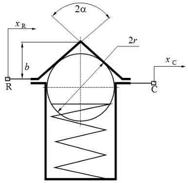
Translational detent dimensioning diagram

Here,

  • b is the notch depth.

  • r is the ball radius.

  • α is the notch half angle.

Depending on how you parameterize the block, the shear force model is defined by geometric and spring parameters, by the peak force and notch width, or by a table lookup that specifies relative displacement versus force.

Translational Detent Parameterization

When you set Parameterization to By peak force and notch width, the block ensures that the force-relative displacement curve provides a continuous force and force derivative over the detent region. The peak forces are halfway between the detent center and detent edge, as the figure shows.

Detent force profile plot

When you set Parameterization to By geometry, the block uses four regions to define the shear force. The figure displays these regions.
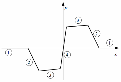
Translational detent region diagram. The regions are 1, 2, 3, 4, 3, 2, 1, where region 4 crosses the y-axis at the origin from negative to positive. There is more information in the table below.

Because the ball is spherical and the notch is symmetric, the horizontal force versus displacement function is symmetric about the origin.

The table describes the ball position, contact angle, and shear force contributions for each region.

RegionBall Position and Contact AngleShear Force
1The ball is outside of the conical notch. The contact angle is vertical.Viscous damping and kinetic friction only. No spring contribution.
2The ball is entering notch and is in contact with the notch corner. The contact angle rotates from vertical.Spring, viscous damping, and kinetic friction contributions. Peaks at transition from region 2 to region 3.
3The ball slides along the face of the notch. The contact angle is constant.Force decreases as spring extends until reaching the spring preload force.
4The ball moves from one face to the other. The contact angle switches direction.Force switches direction. The shear reversal region width controls how smooth this switch is.

When you set Parameterization to By table lookup, you can create an arbitrary function that relates shear force to relative displacement. If you create such a function, consider these best practices.

Energy Conservation

To ensure that the detent conserves energy, the integral of the force-relative displacement curve must be zero.

Simulation Performance

Avoid discontinuities in the force-relative displacement function. The most important requirement is to have a shear reversal region of nonzero width, analogous to region 4 in the geometric parameterization.

Assumptions and Limitations

  • The block does not account for inertia. Add mass externally to the R and C ports.

  • When you set Parameterization to By peak force and notch width or By table lookup, the kinetic friction is independent of the detent normal force.

Examples

Ports

Conserving

expand all

Mechanical translational conserving port associated with the case.

Mechanical translational conserving port associated with the slider or rod.

Parameters

expand all

Detent Characteristics

Detent characteristic specification.

  • By peak force and notch width — Specify detent characteristics by the peak shear force and the notch width.

  • By table lookup — Define the detent characteristics by one-dimensional table lookup based on the relative displacement between the slider and case.

  • By geometry — Define the detent characteristics by ball-notch geometry and dynamics.

Peak shear force developed inside the detent.

Dependencies

To enable this parameter, set Parameterization to By peak force and notch width.

Width of the region where the shear force develops.

Dependencies

To enable this parameter, set Parameterization to By peak force and notch width.

Vector of input relative displacements that corresponds to the values in the Force vector parameter. This vector must be same the size as the Force vector parameter. You must specify the displacements in increasing order.

Dependencies

To enable this parameter, set Parameterization to By table lookup.

Vector of input values for the shear force that corresponds to the Relative displacement vector parameter.

Dependencies

To enable this parameter, set Parameterization to By table lookup.

Lookup table breakpoint interpolation. The block uses the tablelookup function to model nonlinearity by using array data to map input values to output values.

  • Linear — Select this option for the lowest computational cost.

  • Smooth — Select this option to produce a continuous curve with continuous first-order derivatives.

For more information, see tablelookup.

Dependencies

To enable this parameter, set Parameterization to By table lookup.

Cross sectional diameter of the ball..

Dependencies

To enable this parameter, set Parameterization to By geometry.

Full angle of the notch.

Dependencies

To enable this parameter, set Parameterization to By geometry.

Depth of the notch in the slider.

Dependencies

To enable this parameter, set Parameterization to By geometry.

Force to preload the detent spring.

Dependencies

To enable this parameter, set Parameterization to By geometry.

Stiffness of the detent spring.

Dependencies

To enable this parameter, set Parameterization to By geometry.

Width of the region between notch faces.

Dependencies

To enable this parameter, set Parameterization to By geometry.

Relative displacement of the slider and case when simulation starts.

Friction

Viscous friction coefficient for the ball-notch contact.

Ratio by which to compute kinetic friction. The kinetic friction is this ratio multiplied by the peak shear force.

Dependencies

To enable this parameter, set Parameterization to By peak force and notch width or By table lookup.

Kinetic friction coefficient for the ball-notch contact.

Dependencies

To enable this parameter, set Parameterization to By geometry.

Relative velocity required for peak kinetic friction in the detent.

Extended Capabilities

C/C++ Code Generation
Generate C and C++ code using Simulink® Coder™.

Version History

Introduced in R2011b

Go to top of page