Main Content

Thermal ROM

R2026b

Reduced-order thermal model using state-space representation

Since R2026b

  • Thermal ROM block

Libraries:
Simscape / Battery / Thermal

Description

The Thermal ROM block implements a reduced-order model (ROM) of the thermal behavior of a battery system, using a state-space representation. The model captures the thermal dynamics of a battery cell and its interaction with external cooling or heating systems.

Accurate thermal modeling helps with analyzing the performance, safety, and lifetime of electrochemical cells. This block enables you to:

  • Integrate a high‑fidelity thermal model of a battery cell into your Simscape™ model.

  • Interface the thermal model with a Battery Equivalent Circuit or Battery Single Particle block that represents an electrical model.

  • Support external heat transfer mechanisms, such as heat exchange with the ambient environment or with a cooling plate.

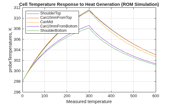
  • Monitor temperatures at specific locations within the cell.

Note

The Thermal ROM block assumes heat-flow inputs in watts (W) and temperature states and outputs in kelvin (K). The block enforces these units internally, and the state‑space matrices are valid only under this convention. If a thermal ROM using different units (for example, heat‑flow in kilowatts or temperature in degrees Celsius), then to prevent incorrect temperature predictions, you must rescale the matrices and apply any required offsets before using the matrices with the Thermal ROM block.

Equations

These state-space equations describe the cell thermal dynamics:

Ex˙(t)=Ax(t)+Bu(t)  y(t)=Cx(t)+Du(t)

where

  • x(t) is the thermal state vector, representing the reduced-order temperature states.

  • u(t) is the heat-flow input vector, comprising the cell heat generation and the external heat flow inputs. The block constructs the input vector u(t) by concatenating the heat‑flow rates applied at the Cell and Interface thermal conserving ports:

    u(t)=[Q˙cellQ˙interface].

    Each element of u(t) corresponds to the heat-flow rate applied at one thermal element of the Cell or Interface port.

  • y(t) is the output vector, comprising the cell temperature, probe temperatures, and external interface temperatures:

    y(t)=[TcellTprobeTinterface].

  • E is the thermal mass matrix that defines the thermal capacitance of the system.

  • A is the thermal stiffness matrix that defines the thermal conductance between thermal states.

  • B is the heat-flow input matrix that models the heat distribution. This matrix specifies how the heat‑flow rate at a specific thermal node influences the thermal states of the ROM.

  • C is the temperature output matrix that defines how the thermal states map to the temperature at a specific thermal node.

  • D is the direct feedthrough matrix and is internally set to zero, because direct feedthrough is typically not modeled in thermal models.

The block constructs the B matrix from parameters that represent different thermal dynamics and correspond directly to thermal conserving ports:

  • Cell heat-flow input matrix (B) — Volume-specific heat generation from the battery cell, Bcell.

  • Interface heat-flow input matrix (B) — Heat exchange at the thermal boundary conditions, Binterface.

Internally, the block assembles the full heat-flow input matrix by horizontally concatenating these matrices:

B=[BcellBinterface].

Each column of the combined B matrix corresponds to one thermal element of the associated Cell or Interface thermal port and defines how the heat flow at that thermal element influences the thermal states. The order of the columns must match the orders of the elements in the Cell and Interface port arrays.

The C matrix contains the mapping between the thermal state vector and the output vector, enabling temperature reporting at specified locations. The block constructs the C matrix from these parameters:

  • Cell temperature output matrix (C) — Volumetric average temperature of the battery cell, Ccell.

  • Probe temperature output matrix (C) — Temperature at the specified monitoring points, Cprobe.

  • Interface temperature output matrix (C) — Interface temperatures for the thermal boundary conditions, Cinterface.

Internally, the block assembles the full temperature output matrix by vertically concatenating these matrices:

C=[CcellCprobeCinterface].

Each row maps the thermal states to the temperature at one output location. The order of the rows of the C matrix defines the ordering of temperatures in the output vector y(t).

When generating a reduced-order thermal model, if you have only a single, combined heat-flow input matrix Bcombined and a single, combined temperature output matrix Ccombined, then you must partition each of these two matrices into separate cell, probe, and interface matrices before specifying the block parameters. To partition the matrices, follow these steps:

  1. Determine how many thermal elements are associated with the Cell and Interface thermal ports, and how many temperature outputs are defined for the cell, probe, and interface locations.

  2. Partition the matrices according to those element counts.

  3. Assign the resulting submatrices to the corresponding block parameters.

Probe nodes do not apply heat flow and do not contribute columns to the heat‑flow input matrix.

Examples

expand all

Split a combined heat-flow input matrix B and a combined temperature output matrix C that you obtained from external reduced-order thermal modeling workflows. Then, use these matrices as parameters for the Thermal ROM block.

An external ROM workflow produces this state-space model:

Ex.(t)=Ax(t)+Bcombinedu(t)y(t)=Ccombinedx(t)

where the reduced‑order model has 4 thermal states:

x(t)∈ℝ4

Suppose that you want to parameterize the Thermal ROM block to represent a battery cell using a reduced-order thermal model with these characteristics:

  • One cell thermal connection that represents lumped heat generation from the electrochemical model.

  • Two interface thermal connections that represent the connections to the top and bottom cooling plates.

  • Three internal probe temperature outputs that monitor internal temperature gradients.

The ROM workflow provides a single combined heat-flow input matrix, Bcombined:

Bcombined=[b11b12b13b21b22b23b31b32b33b41b42b43].

Each column corresponds to one heat-flow input, but the ROM workflow does not label these columns by physical meaning. Based on the ROM setup, the three input columns correspond to:

  • Column 1 — One heat-flow input associated with the Cell port.

  • Column 2 and 3 — Two heat-flow inputs associated with the Interface port.

To parameterize the Thermal ROM block, split the combined matrix by columns and assign these columns to the Cell heat flow input matrix (B) and Interface heat flow input matrix (B) parameters:

Cell heat flow input matrix (B)=[b11b21b31b41]Interface heat flow input matrix (B)=[b12b13b22b23b32b33b42b43]

The number of columns in each matrix defines the number of thermal elements for the corresponding thermal node.

The external ROM workflow also provides a single combined temperature output matrix, Ccombined:

Ccombined=[c11c12c13c14p11p12p13p14p21p22p23p24p31p32p33p34t11t12t13t14t21t22t23t24].

Each row corresponds to one temperature output. Based on the ROM setup, the rows correspond to temperatures in the Thermal ROM block as follows:

  • Row 1 — One cell temperature

  • Rows 2 through 4 — Three probe temperatures

  • Rows 5 and 6 — Two interface temperatures

To parameterize the Thermal ROM block, split the combined matrix by rows and assign these rows to the Cell temperature output matrix (C), Probe temperature output matrix (C), and Interface temperature output matrix (C) parameters:

Cell temperature output matrix (C)=[c11c12c13c14]Probe temperature output matrix (C)=[p11p12p13p14p21p22p23p24p31p32p33p34]Interface temperature output matrix (C)=[t11t12t13t14t21t22t23t24]

Probe temperatures are output‑only quantities. The block does not associate them with any thermal conserving port.

By using these matrices, the Thermal ROM block internally constructs the state-space matrices:

B=[Cell heat flow input matrix (B)Interface heat flow input matrix (B)]C=[Cell temperature output matrix (C)Probe temperature output matrix (C)Interface temperature output matrix (C)]

The resulting state-space input and output vectors are:

u(t)=[Q˙CellQ˙Interface,1Q˙Interface,2]

y(t)=[TCellTProbe,1TProbe,2TProbe,3TInterface,1TInterface,2]

Check the dimensional consistency of the matrices. For each thermal node, the number of rows of the corresponding temperature output matrix must be equal to the number of columns of the associated heat‑flow input matrix.

Columns of Cell heat flow input matrix=Rows of Cell temperature output matrix=1Columns of Interface heat flow input matrix=Rows of Interface temperature output matrix=2

Probe temperature outputs contribute only rows to the temperature output matrix and do not have corresponding heat‑flow inputs.

Extended Examples

Ports

Conserving

expand all

Both Cell and Interface thermal conserving ports can represent multiple thermal elements. The dimensions of the corresponding heat‑flow input and temperature output matrices determine the number of elements for each port.

For each thermal node:

  • The number of columns of the heat‑flow input matrix defines the number of thermal elements.

  • The number of rows of a temperature output matrix must be equal to the number of columns of the associated heat‑flow input matrix.

For example, if the Cell heat‑flow input matrix has M columns, the Cell temperature output matrix must have M rows. Each column-row pair corresponds to one Cell thermal element.

Thermal conserving port associated with the thermal connection to the electrical model.

Thermal conserving port associated with the external thermal connections for cooling or heating. The value at this port can be a scalar or an array of thermal nodes. This table shows the relationship between the external thermal option and the connection to the thermal node in the array.

Thermal OptionNode Connection
Cooling platesThe first element of the Interface port array connects to the top cooling plate. The last element of the Interface port array connects to the bottom cooling plate.
Ambient thermal pathEach element of the Interface port array connects to an individual thermal resistance. Then, the elements all connect to a single, scalar top-level thermal node.
Coolant thermal path
Intercell thermal pathEach element of the Interface port array connects to the corresponding element of the adjacent cell through a thermal resistor or thermal radiative heat transfer block.
Intercell radiative path
Serpentine cooling plateAll elements of the Interface port array connect in series.

Parameters

expand all

To edit block parameters interactively, use the Property Inspector. From the Simulink® Toolstrip, on the Simulation tab, in the Prepare gallery, select Property Inspector.

Main

Thermal conductances between thermal nodes, specified as an N-by-N matrix where N is the length of the Initial state vector parameter value.

Thermal capacitances, specified as an N-by-N matrix where N is the length of the Initial state vector parameter value.

Probe

Temperature at the specified monitoring points. The number of columns of this parameter value must be equal to the length of the Initial state vector parameter value.

Probe temperature outputs report temperatures at predefined internal locations of the reduced‑order model. Probe outputs do not apply or receive heat flow. They contribute only to the temperature output matrix C, not to the heat‑flow input matrix B.

Cell Interface

Volume-specific heat generation from the battery cell, specified as an N-by-M matrix, where N is the length of the Initial state vector parameter value and M is the number of rows of the Cell temperature output matrix (C) parameter value.

Volumetric average temperature of the battery cell. The number of columns of this matrix must be equal to the length of the Initial state vector parameter value.

External Interface

Heat exchange at the thermal boundary conditions, where N is the length of the Initial state vector parameter value and M is the number of rows of the Interface temperature output matrix (C) parameter value.

Interface temperatures for the thermal boundary conditions. The number of columns of this matrix must be equal to the length of the Initial state vector parameter value.

Initial Targets

Initial states.

Extended Capabilities

expand all

C/C++ Code Generation
Generate C and C++ code using Simulink® Coder™.

Version History

Introduced in R2026b