Main Content

Reservoir (MA)

R2026b

Boundary conditions for moist air network at constant or time-varying pressure, temperature, moisture, and trace gas levels

  • Reservoir (MA) block

Libraries:
Simscape / Foundation Library / Moist Air / Elements

Description

The Reservoir (MA) block sets boundary conditions in a moist air network. Port A, a moist air conserving port, represents the reservoir inlet.

The volume of moist air inside the reservoir is assumed infinite. Therefore, the flow is assumed quasi-steady.

The moist air leaves the reservoir at the reservoir pressure, temperature, specific humidity, and trace gas mass fraction. Moist air enters the reservoir at the reservoir pressure, but the temperature, specific humidity, and trace gas mass fraction are determined by the moist air network upstream.

The block provides two ways to specify pressure and temperature:

  • Static pressure and static temperature — To simplify the calculations, the block assumes that there is no difference between the pressure and temperature of moist air inside the reservoir and at the exit port. This assumption is valid for applications with low-speed compressible flow, such as HVAC systems. You can also use it to simulate a portion of a system based on measured pressure and temperature at the boundary, that is, on the static pressure and static temperature.

  • Total pressure and total temperature — This option assumes that the moist air starts at rest and speeds up toward the exit port, which results in a reduction in pressure and temperature. Use this modeling option for applications with high-speed compressible flows, such as aerospace, or for fluid dynamics analysis.

    Total pressure and total temperature are the pressure and temperature of moist air at rest inside the reservoir. These quantities are also sometimes called stagnation pressure and temperature. They are related to the pressure and temperature at the reservoir port A by these equations

    h(ptotal,Ttotal)=h(pA,ToutA)+[min(m˙A,0)]22[ρ(pA,ToutA)SA]2s(ptotal,Ttotal)=s(pA,ToutA)

    where:

    • ptotal is the total, or stagnation, pressure.

    • Ttotal is the total, or stagnation, temperature.

    • pA is the pressure at the reservoir port.

    • ToutA is the temperature at the reservoir port as the moist air flows out of reservoir. If the moist air flows into the reservoir, its temperature is determined by the moist air network upstream.

    • h is the specific enthalpy.

    • s is the specific entropy.

    • m˙A is the mass flow rate of moist air through the reservoir port. When the moist air leaves the reservoir, m˙A is negative. The min term in the specific enthalpy equation assumes a value corresponding to the mass flow rate of moist air when the moist air leaves the reservoir. When the moist air enters the reservoir, this term is 0.

    • ρ is density.

    • SA is the cross-sectional area at the reservoir port.

Your choice between static or total pressure and temperature has no effect on the mass fractions of the moist air mixture.

You specify the reservoir pressure, temperature, amount of humidity, amount of trace gas, and amount of water droplets with block parameter values or physical signals. The block ignores parameters and physical signals related to trace gas or water droplets if in the Moist Air Properties (MA) block, Trace gas model is None or the Enable entrained water droplets check box is cleared, respectively.

You can specify humidity as one of:

  • Relative humidity, φw

  • Specific humidity, xw

  • Water vapor mole fraction, yw

  • Humidity ratio, rw

  • Wet-bulb temperature, Tw

You can specify trace gas as one of:

  • Trace gas mass fraction, xg

  • Trace gas mole fraction, yg

These humidity and trace gas quantities are related to each other as follows:

φw=ywppwsyw=xwRwRrw=xw1xwyg=xgRgRxa+xw+xg=1R=xaRa+xwRw+xgRg

where:

  • p is the pressure.

  • R is the specific gas constant.

Subscripts a, w, and g indicate the properties of dry air, water vapor, and trace gas, respectively. Subscript ws indicates water vapor at saturation.

The block calculates the wet-bulb temperature implicitly as

xw=(1xg(T))(ha(Tw)ha(T))+xg(hg(Tw)hg(T))+xws(Tw)1xws(Tw)Δhfg(Tw)(ha(Tw)ha(T))(hw(Tw)hw(T))+11xws(Tw)Δhfg(Tw)

where:

  • T is the temperature.

  • Tw is the wet-bulb temperature.

  • xw(T) is the specific humidity.

  • xg(T) is the trace gas mass fraction.

  • xws(Tw) is the specific humidity of saturation at the wet bulb temperature.

  • ha(T) is the specific enthalpy of the dry air.

  • ha(Tw) is the specific enthalpy of the dry air at the wet bulb temperature.

  • hg(T) is the specific enthalpy of the trace gas.

  • hg(Tw) is the specific enthalpy of the trace gas at the wet bulb temperature.

  • hw(T) is the specific enthalpy of the water vapor.

  • hw(Tw) is the specific enthalpy of the water vapor at the wet bulb temperature.

  • Δhfg(Tw) is the specific enthalpy of vaporization of water vapor at the wet-bulb temperature.

Examples
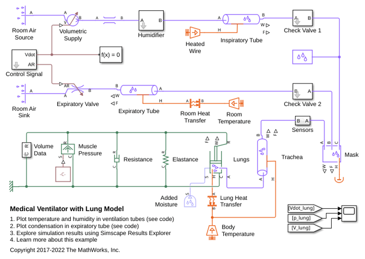
Ports

Input

expand all

Physical signal port that controls the reservoir pressure.

Dependencies

To enable this port, select Provide input signal for pressure.

Physical signal port that controls the reservoir temperature.

Dependencies

To enable this port, select Provide input signal for temperature.

Physical signal port that controls the reservoir humidity level. To select the quantity that the control signal represents, use the Humidity specification parameter.

Dependencies

To enable this port, select Provide input signal for humidity and set the Humidity specification parameter to one of theses options:

  • Relative humidity

  • Specific humidity

  • Mole fraction

  • Humidity ratio

Physical signal port that controls the reservoir wet-bulb temperature.

Dependencies

To enable this port, select Provide input signal for humidity and set the Humidity specification parameter to Wet-bulb temperature.

Physical signal port that controls the reservoir trace gas level. To select the quantity that the control signal represents, use the Trace gas specification parameter.

Dependencies

To enable this port, select Provide input signal for trace gas.

Physical signal port that controls the reservoir mass ratio of water droplets to moist air.

Dependencies

To enable this port, select Provide input signal for water droplets.

Conserving

expand all

Moist air conserving port associated with the reservoir inlet.

Parameters

expand all

Select quantities to use for the reservoir pressure and temperature:

  • Static pressure and static temperature — Specify pressure and temperature as boundary conditions at the reservoir port. Use this modeling option for applications with low-speed compressible flow, such as HVAC systems. You can also use it to simulate a portion of a system based on measured pressure and temperature at the boundary.

  • Total pressure and total temperature — Specify pressure and temperature of gas at rest inside the reservoir. As the moist air speeds up towards the exit port, its movement results in a reduction in pressure and temperature. Use this modeling option for applications with high-speed compressible flows, such as aerospace, or for fluid dynamics analysis.

Method to use to specify the pressure in the reservoir. If you clear this check box, the block models pressure based on the value of the Reservoir pressure parameter or atmospheric pressure. If you select this check box, the block models pressure based on the value of the signal at port P.

Specification method for the reservoir pressure:

  • Atmospheric pressure — Use the atmospheric pressure specified by the Moist Air Properties (MA) block connected to the circuit.

  • Specified pressure — Specify a value by using the Reservoir pressure parameter.

Dependencies

To enable this parameter, clear the Provide input signal for pressure check box.

Pressure in the reservoir. This pressure remains constant during simulation.

Dependencies

To enable this parameter, clear the Provide input signal for pressure check box and set Pressure specification to Specified pressure.

Method to use to specify the temperature in the reservoir. If you clear this check box, the block models temperature based on the value of the Reservoir temperature parameter or atmospheric temperature. If you select this check box, the block models temperature based on the value of the signal at port T.

Specification method for the reservoir temperature:

  • Atmospheric temperature — Use the atmospheric temperature specified by the Moist Air Properties (MA) block connected to the circuit.

  • Specified temperature — Specify a value by using the Reservoir temperature parameter.

Dependencies

To enable this parameter, clear the Provide input signal for temperature check box.

Temperature in the reservoir. This temperature remains constant during simulation.

Dependencies

To enable this parameter, clear the Provide input signal for temperature check box and set Temperature specification to Specified temperature.

Method to use to specify the humidity in the reservoir. If you clear this check box, the block models humidity based on the value of the based on the value of the Humidity specification parameter. If you select this check box, the block models humidity based on the value of the signal at port W or Tw.

Specification method for the reservoir humidity:

  • Relative humidity ― Specify humidity using the relative humidity.

  • Specific humidity ― Specify humidity using the specific humidity.

  • Mole fraction ― Specify humidity using the water vapor mole fraction.

  • Humidity ratio ― Specify humidity using the humidity ratio.

  • Wet-bulb temperature ― Specify humidity using the wet-bulb temperature.

Relative humidity in the reservoir. This value remains constant during simulation.

Dependencies

To enable this parameter, clear the Provide input signal for humidity check box and set Humidity specification to Relative humidity.

Specific humidity in the reservoir. This value remains constant during simulation.

Dependencies

To enable this parameter, clear the Provide input signal for humidity check box and set Humidity specification to Specific humidity.

Water vapor mole fraction in the reservoir. This value remains constant during simulation.

Dependencies

To enable this parameter, clear the Provide input signal for humidity check box and set Humidity specification to Mole fraction.

Humidity ratio in the reservoir. This value remains constant during simulation.

Dependencies

To enable this parameter, clear the Provide input signal for humidity check box and set Humidity specification to Humidity ratio.

Wet-bulb temperature in the reservoir. This value remains constant during simulation.

Dependencies

To enable this parameter, clear the Provide input signal for humidity check box and set Humidity specification to Wet-bulb temperature.

Method to use to specify the trace gas in the reservoir. If you clear this check box, the block models trace gas based on the value of the Reservoir trace gas mass fraction or Reservoir trace gas mole fraction parameters. If you select this check box, the block models trace gas based on the value of the signal at port G.

Specification method for the reservoir trace gas:

  • Mass fraction ― Specify the trace gas mass fraction.

  • Mole fraction ― Specify the trace gas mole fraction.

Trace gas mass fraction in the reservoir. This value remains constant during simulation.

Dependencies

To enable this parameter, select Provide input signal for trace gas and set Trace gas specification to Mass fraction.

Trace gas mole fraction in the reservoir. This value remains constant during simulation.

Dependencies

To enable this parameter, select Provide input signal for trace gas and set Trace gas specification to Mole fraction.

Method to use to specify the water droplets mass ratio in the reservoir. If you clear this check box, the block models water droplets based on the value of the Reservoir mass ratio of water droplets to moist air parameter. If you select this check box, the block models water droplets based on the value of the signal at port D.

Mass ratio of water droplets to moist air in the reservoir.

Dependencies

To enable this parameter, clear the Provide input signal for water droplets check box.

Relative humidity above which condensation occurs.

Cross-sectional area of the reservoir inlet.

Action for the block to take when the input signal values are outside of valid range:

  • Limit to valid values ― The block limits the input signal to the minimum or maximum valid values, but does not issue a warning.

  • Warn and limit to valid values ― The block issues a warning and limits the input signal to the minimum or maximum valid values.

  • Error ― Simulation stops with an error.

Dependencies

To enable this parameter, select at least one of these parameters:

  • Provide input signal for pressure

  • Provide input signal for temperature

  • Provide input signal for humidity

  • Provide input signal for trace gas

  • Provide input signal for water droplets

Extended Capabilities

expand all

C/C++ Code Generation
Generate C and C++ code using Simulink® Coder™.

Version History

Introduced in R2018a

expand all