Access Data Store at Higher Level in Model Hierarchy
This example shows how to access the data stored in the Data Store Memory block at a higher level in the model hierarchy.
In this example:
The model has two hierarchical components: the top-level model
DataStoreMemoryTopand the referenced modelDataStoreMemoryBot. The Data Store Memory block at the top-level model defines the data storeAAA.An Event Scheduler creates function-call events based on the sine wave amplitude.
Based on the function-call events, the Data Store Read and the Data Store Write blocks within the referenced model access the data store
AAAat the top-level model.

Configure Blocks Inside the Referenced Model
At the top-level model, a Model block references to the DataStoreMemoryBot model. To allow the Data Store Read and Data Store Write blocks inside the referenced model to access the data store:
Place a Data Store Memory block inside a referenced model
DataStoreMemoryBot. In the Data Store Memory block dialog box, select Data store reference. Set Data store name to the same value as the data store name:AAA.
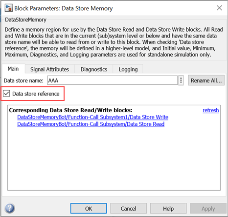
On the Signal Attributes tab, specify the Data type as
int32, Dimensions as[1 1], and Signal type asreal. These values are the same values as for the input signalmySig.

Upon receiving the Read function-call signal at the read port of the Model block, the Data Store Read block reads data from the data store. The output is displayed at the Scope block. Similarly, when the model receives the Write function-call signal at the write port of the Model block, the input signal value 5 is multiplied by the Gain parameter value 2, and the Data Store Write block writes to the data store.

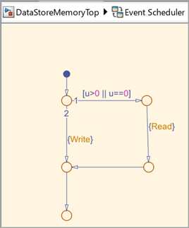
Model Function-Call Events Using Event Scheduler
Use a Stateflow® chart to model an event schedule that generates the Read and Write function-call events based on the sine wave amplitude. These function-call events control the execution of the DataStoreMemoryTop model.
Review Results
Simulate the model.
out = sim('DataStoreMemoryTop');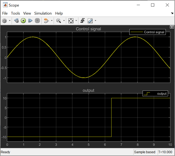
The model executes based on function-call events. In the Scope block, the Control Signal (top row) and Output Signal (bottom row) represent the input to the Event Scheduler and the model output, respectively.
Between 0 to 3.2 s (approximately), the
Control Signalvalue is either 0 or positive, which triggers theReadfunction-call from the Event Scheduler. Subsequently, the Data Store Read block reads the Initial value (-10) of the Data Store Memory block defined in the top-level model. The Scope blocks displays theOutput Signalvalue as-10until the nextReadevent is triggered at 6.4 s.Between 3.2 s to 6.4 s (approximately), the negative value of the
Control Signaltriggers theWritefunction-call event from the Event Scheduler. Subsequently, theControl Signalvalue is multiplied by theGainparameter and the Data Store Write block writes this value to the data store.Between 6.4 s to 9.5 s (approximately), the Data Store Read block reads the value from the data store and displays the output in the Scope block.
See Also
Data Store Memory | Data Store Read | Data Store Write | Function-Call Subsystem
Topics
- Create Stateflow Charts (Stateflow)
- Using Function-Call Subsystems
- Code Generation for Data Store References (Simulink Coder)