Magnetic Control for Detumbling of Satellite
R2026bThis example shows how to model magnetic control for the detumbling of a CubeSat using Aerospace Blockset™.
After separation from a launch vehicle, a satellite often enters a tumbling state due to residual angular rates imparted during deployment. Before the satellite can begin nominal operations, it must reduce these angular rates to near zero, a process known as detumbling. In this example, magnetorquers serve as control actuators for detumbling. Magnetorquers are electromagnetic coils that interact with Earth's magnetic field to produce control torques. They are lightweight, reliable, and require no expendable propellant, making them well-suited for detumbling small satellites in low Earth orbit.
Open Model
Open the Simulink® model. The model is organized into three areas: Spacecraft Dynamics, Magnetic Control, and Visualization.
mdl = "SatelliteMagneticDetumble";
open_system(mdl);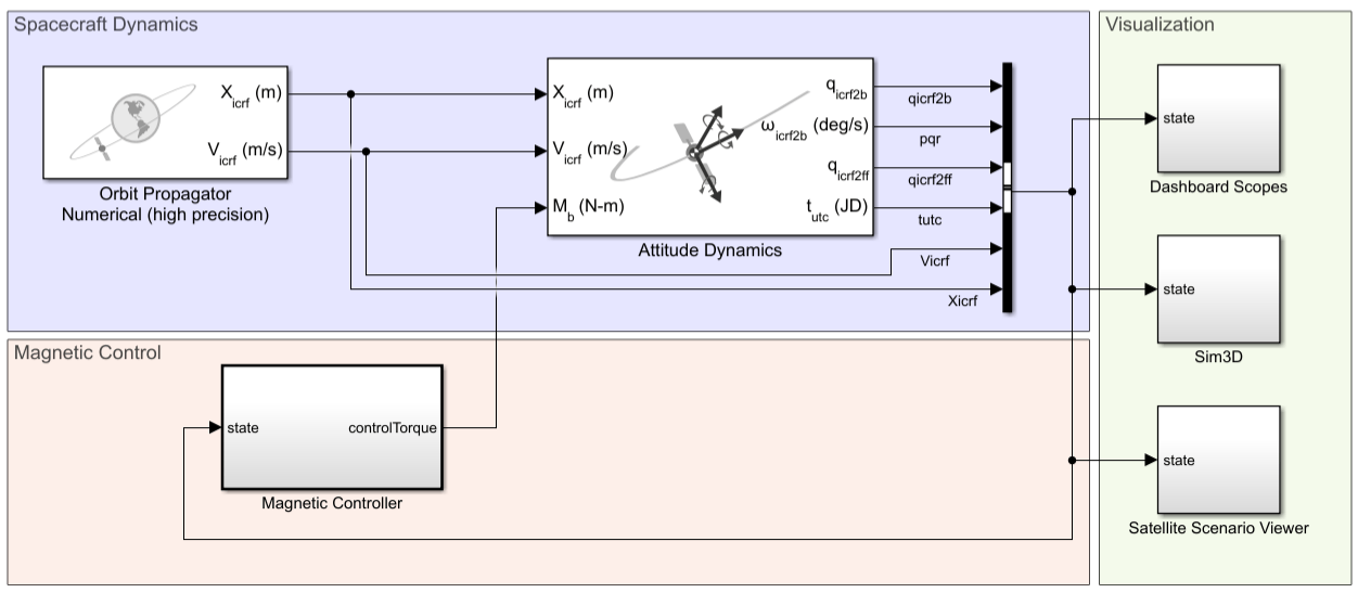
The spacecraft dynamics are modeled by separating the orbital motion and attitude motion of the satellite into two coupled blocks: the Orbit Propagator block and the Attitude Dynamics block. the Magnetic Controller subsystem implements the bang-bang B-dot algorithm for satellite detumbling. In the Visualization area, the Dashboard Scopes subsystem shows key signals. The Satellite Scenario Viewer subsystem enables post‑run visualizations, and the Sim3D subsystem provides real‑time 3D visualization.
Spacecraft Dynamics
In the Spacecraft Dynamics area, the Orbit Propagator Numerical (high precision) block numerically computes the satellite position and velocity in the inertial ICRF frame with high precision. The block passes these states to the Attitude Dynamics block, which uses numerical integration to propagate the spacecraft rotational motion.
Satellite Properties
This example models a 3U CubeSat-class satellite with a mass of 3.99 kg. Specify the satellite mass and inertia tensor.
cubesat.mass = 3.99;                            % kg
cubesat.inertia = diag([0.033 0.0067 0.033]);   % kg*m^2
Specify the initial tumble rates of the satellite after deployment. These rates represent a typical post-separation tumble.
cubesat.initialRate = [5 7 2]; % deg/sOrbit Configuration
The satellite is in a circular polar orbit: inclination = 90 deg, right ascension of the ascending node (RAAN) = 0 deg. Polar orbits pass near both magnetic poles, providing strong and varying magnetic field vectors that are beneficial for magnetorquer-based control. The orbit is configured on the Orbit Propagator Numerical (high precision) block in the model.
Magnetic Control
To examine the bang-bang B-dot control implementation, open the Magnetic Controller subsystem.
open_system(mdl + "/Magnetic Controller");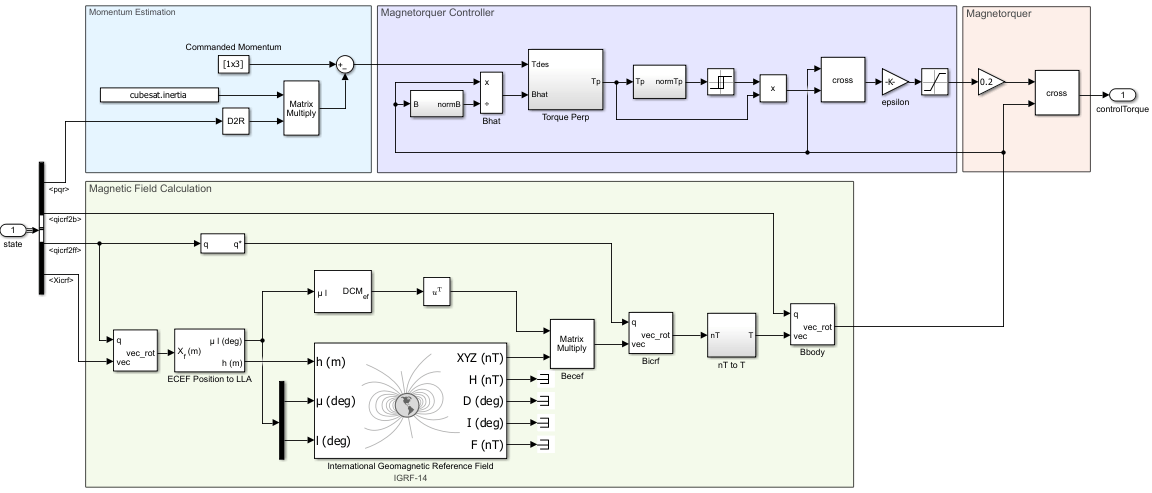
The International Geomagnetic Reference Field block computes the local geomagnetic field vector based on the satellite geodetic position. The field vector is then rotated into the satellite body frame using the attitude quaternion.
Bang-Bang B-Dot Control Law
The bang-bang B-dot control algorithm computes the angular momentum error and produces a control torque perpendicular to the local magnetic field. The term bang-bang refers to the sign function that drives each magnetorquer to its maximum dipole moment in either direction. This example assumes the magnetorquers are aligned with the body x-, y-, and z- axes.
The momentum error is defined as , where is the angular momentum, is the satellite inertia matrix, and is the angular velocity in the body frame. From the Lyapunov stability criterion, a torque is stabilizing if . Therefore, the desired torque direction is . In the model, this direction is computed directly as . For detumbling, .
Magnetorquers cannot generate torque along the direction of the magnetic field . Therefore, the desired torque is projected onto the subspace perpendicular to :
,
where is the unit magnetic field vector in the body frame.
If is the net dipole moment, the resulting torque is . For this torque to be parallel to , a valid dipole direction is:
With that direction, is parallel to .
Because the magnetorquers use bang-bang control, the commanded dipole moment is:
,
where is the maximum dipole moment of each magnetorquer. In a pure bang-bang implementation, the magnetorquer switches abruptly between on and off states. When the momentum error approaches zero, even a slight deviation turns the magnetorquer back on, creating high-frequency on-off cycling (chattering). A relay with hysteresis is applied on to prevent chattering: the controller activates only when the error exceeds an upper threshold and remains active until it falls below a lower threshold, eliminating rapid switching near equilibrium. Additionally, the sign function is replaced with a saturation function:
where is a small gain defining the smoothing threshold. Unlike the sign function, the saturation function replaces the discontinuity at zero with a narrow linear region, which helps the solver avoid zero-crossing issues. However, the relay with hysteresis deactivates the controller before the signal enters this region, ensuring the magnetorquers always operate at full positive or negative dipole moment and never in a partial analog state, reflecting real hardware operation. The torque produced by the magnetorquers is:
Simulate Model
Simulate the model by clicking Run in the Simulink toolstrip. The satellite begins with initial angular rates of [5 7 2] deg/s, and the magnetic controller acts to reduce these rates to near zero over time. The Orbit Propagator block semi-major axis (6,786,000 m) gives an orbital period of approximately 93 minutes by Kepler's third law. The 500 second simulation duration (roughly one-tenth of an orbit) is sufficient to observe full convergence for these initial conditions. Higher initial tumble rates, larger satellites, or equatorial orbits may require longer simulation times to converge.
Visualize and Analyze Results
The model provides multiple visualization mechanisms to help interpret the satellite dynamics and control behavior during simulation.
Dashboard Scopes
The Dashboard Scopes subsystem displays angular velocity components and overall angular rate magnitude in real time using scopes to provide quick feedback on system response. Examine the angular velocity components over time. The bang-bang B-dot controller progressively reduces the tumble rates. For the initial conditions in this example, convergence occurs within a fraction of one orbit. Higher initial rates or equatorial orbits where the magnetic field varies less may require longer convergence times.
Sim3D Animation
The Sim3d subsystem uses Simulink® 3D Animation™ to visualize the CubeSat motion and attitude in real time. Satellite position and orientation are provided to the Simulation 3D CubeSat Pack block during simulation.
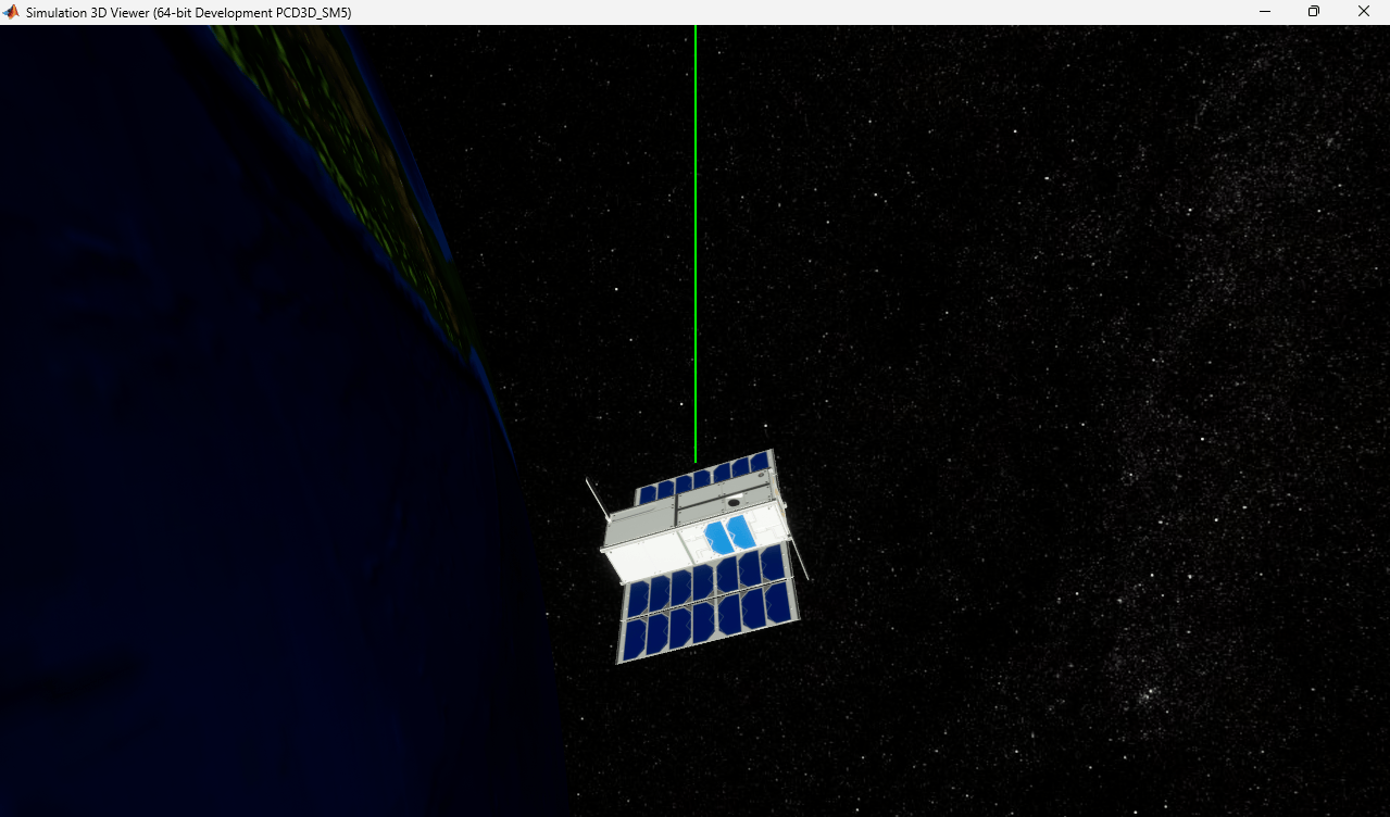
When the Simulation 3D Scene Configuration block is set to the Earth scene, the reference frame is defined as the International Celestial Reference Frame (ICRF). As such, the inertial position is passed directly to the body translation input, Body_T. The attitude quaternion is converted to Euler angles and reordered to match the XYZ rotation sequence required by Simulink 3D Animation.
A Simulation 3D Space Environment block correct orients the Earth and sunlight based on the simulation start time. A Simulation 3D Ray Tracer block visualizes a body‑fixed ray aligned with the CubeSat X‑axis during tumbling motion.
Satellite Scenario Viewer
In the Satellite Scenario Viewer subsystem, the Satellite Scenario Playback records simulation data and opens the Satellite Scenario Viewer after the model simulation completes. The StopFcn model callback creates the satellite scenario from the logged simulation data, assigns a 3D model to the satellite, adds coordinate axes, plays the scenario, and points the camera at the satellite so you can observe the tumbling motion up close.
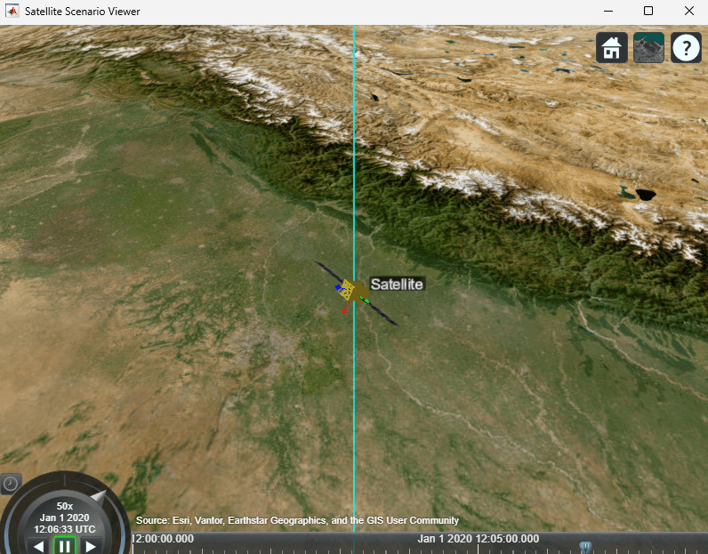
These visualizations illustrate the effectiveness of the bang-bang B-dot control law for magnetorquer-based satellite detumbling. To explore further, try varying the initial tumble rates, orbit configuration, or maximum dipole moment to observe how they affect convergence time.
References
[1] Avanzini, Giulio, and Fabrizio Giulietti. "Magnetic Detumbling of a Rigid Spacecraft." Journal of Guidance, Control, and Dynamics 35, no. 4 (2012): 1326–34. https://doi.org/10.2514/1.53074
[2] Markley, F. L. and Crassidis, J. L. "Magnetic Torque Attitude Control." Fundamentals of Spacecraft Attitude Determination and Control. Space Technology Library. New York: Springer, 2014, pp. 307-312. https://doi.org/10.1007/978-1-4939-0802-8_7
See Also
Blocks
- Orbit Propagator Numerical (high precision) (Aerospace Blockset) | Attitude Dynamics (Aerospace Blockset) | Simulation 3D Scene Configuration (Aerospace Blockset) | Simulation 3D Space Environment (Aerospace Blockset)

